Multifunctional touch smart card

Active Publication Date: 2018-03-13
GOTRUSTID INC
View PDF10 Cites 4 Cited by
  • Summary
  • Abstract
  • Description
  • Claims
  • Application Information

AI Technical Summary

Benefits of technology

[0024]Therefore, in the smart card of the present invention, a touch button is used to replace a conventional mechanical button. The touch button has a small volume and a small thickness and can be disposed overlapping another element or circuit, so that the touch button can be disposed at any position of the smart card. In this way, the appearance of the smart card may be easier to design and more beautiful, and inner space, originally occupied by the mechanical button, of the smart card can be further released. The released space is used to improve the flexibility of the circuit layout, add a function to the smart card, or increase the capacity of a battery, or increas

Problems solved by technology

As functions of smart cards become increasingly complex, the smart cards also have increasingly complex structures.
As can be seen, the inner space of the smart card is very crowded.
However, the inner space of the smart card is limited, and each element occupies some inner space.
Due to technical limitations in the current production process, the mechanical button cannot be disposed overlapping another element or circuit.
Therefore, space for another element to be disposed is compressed, so that the smart card has no space to add a new element, which impedes the development of smart cards.
Therefore, although the contact metal piece takes up certain space of the smart card, the contact metal piece is not fully

Method used


Image

  • Multifunctional touch smart card
  • Multifunctional touch smart card
  • Multifunctional touch smart card

Examples


first embodiment

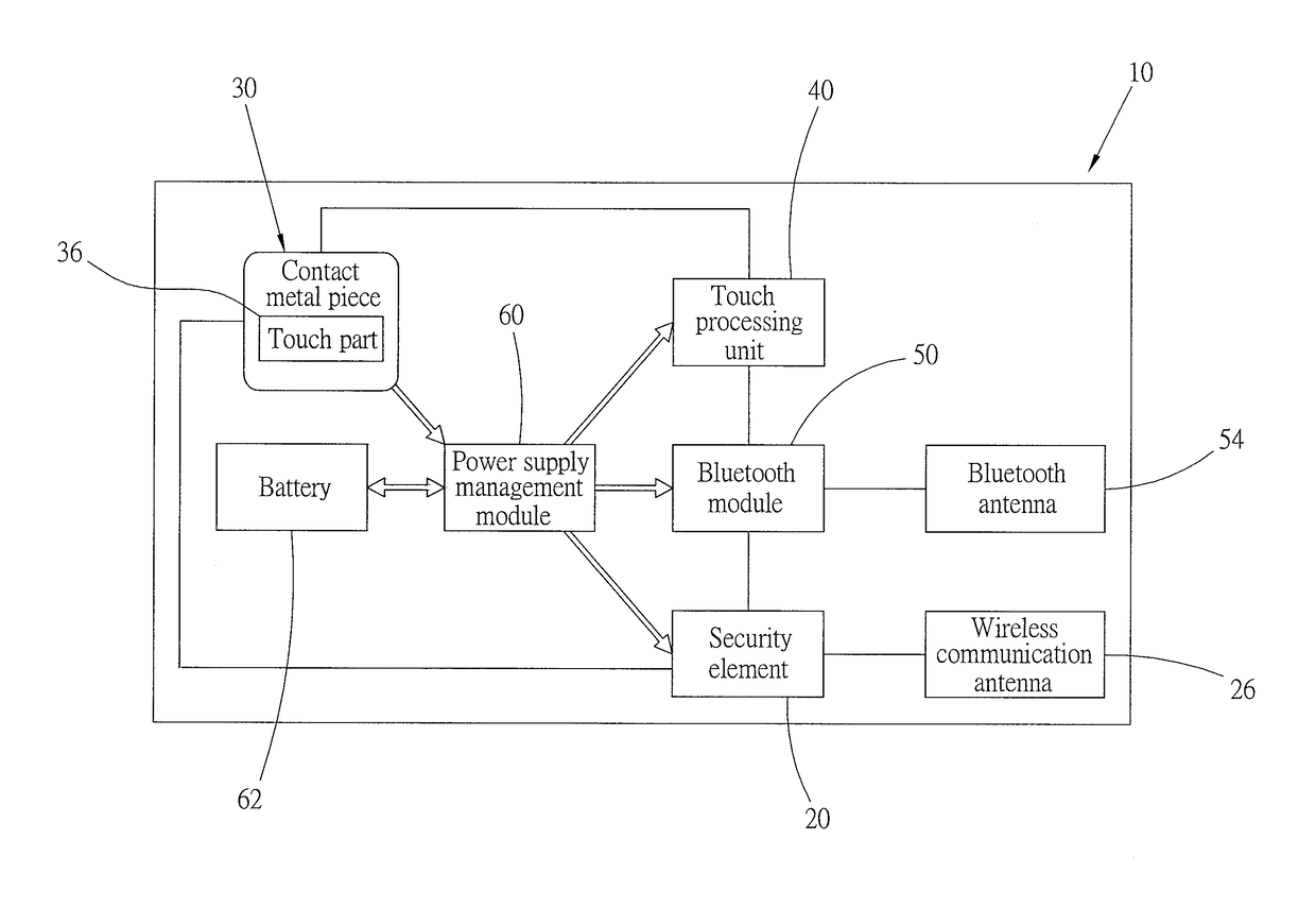
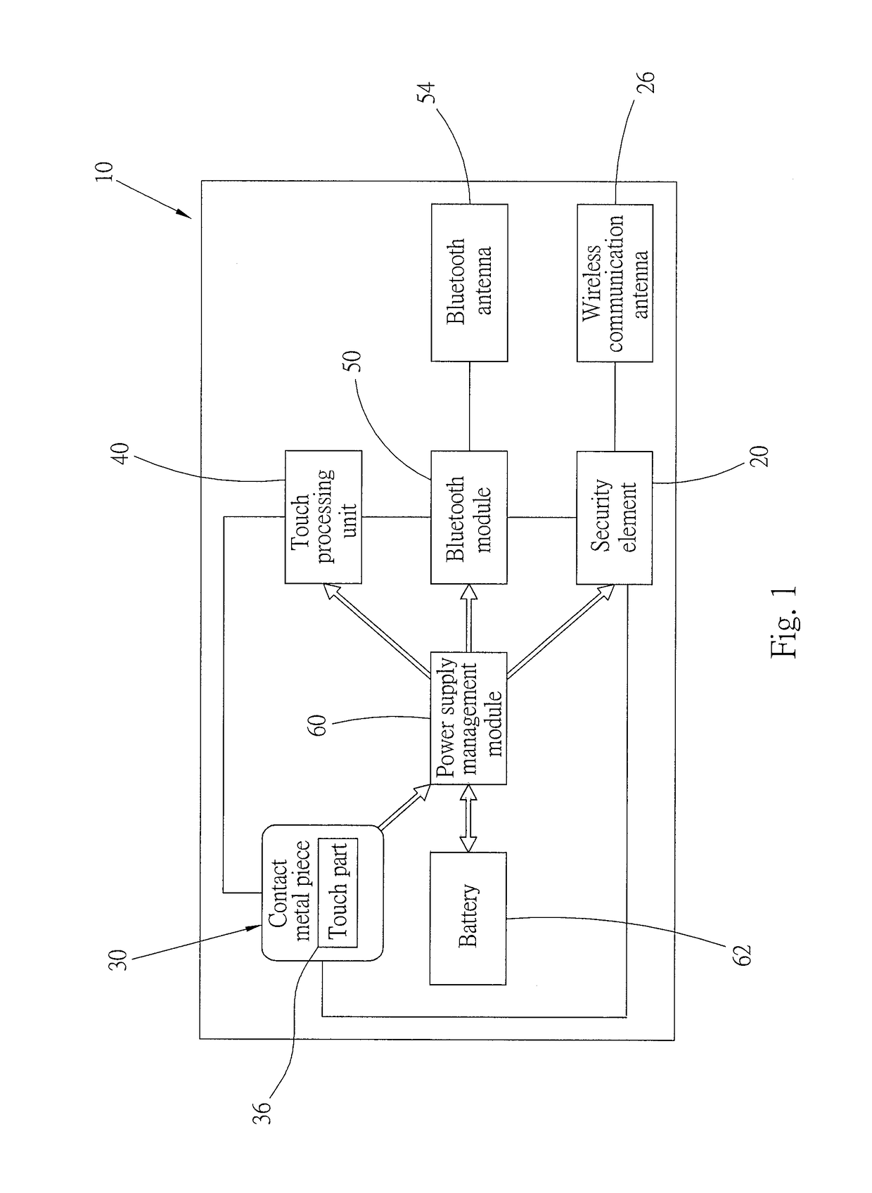
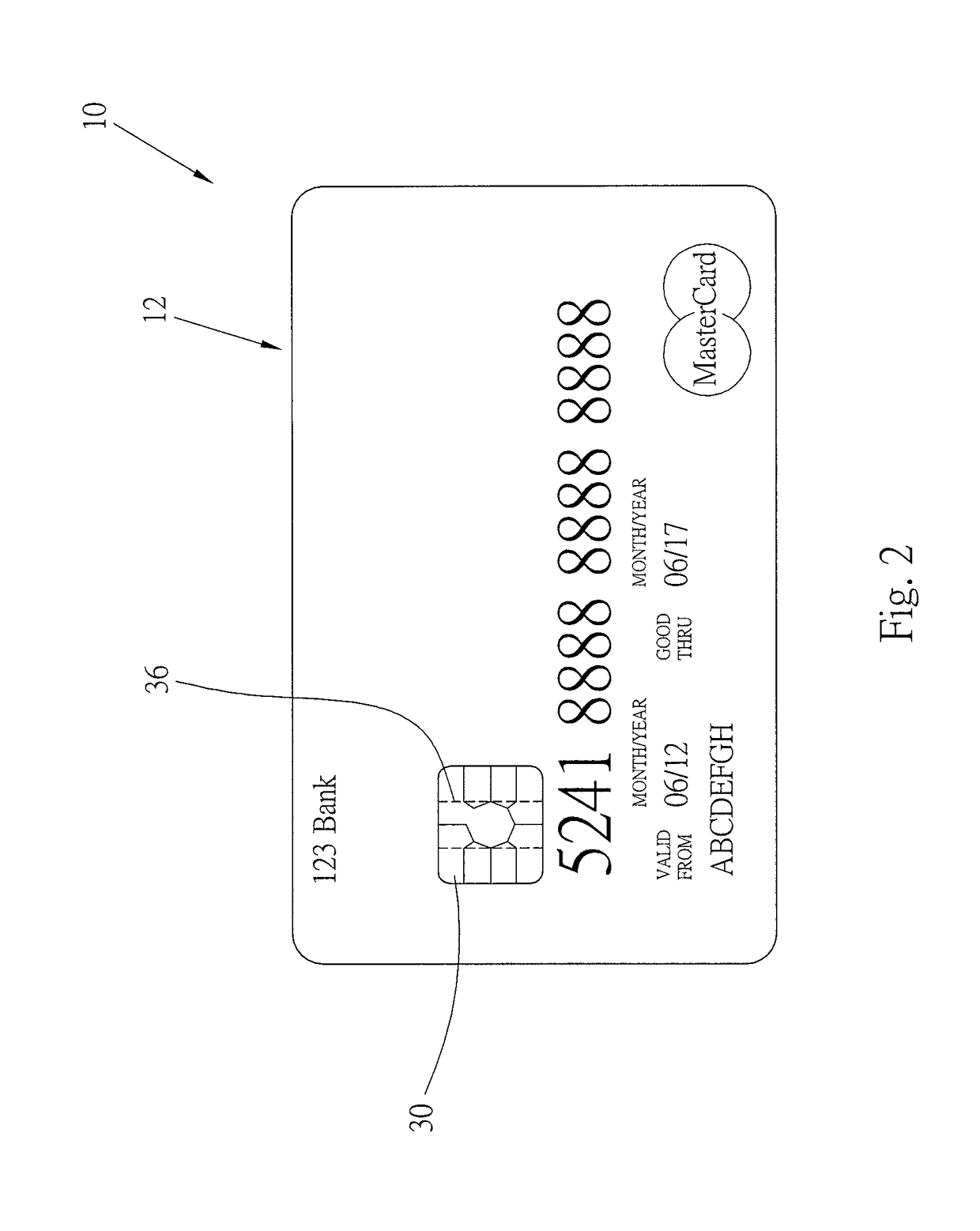
[0055]Referring to FIG. 5 and FIG. 6, a smart card 10′ of a second preferred embodiment of the present invention is shown. A body 12 of the smart card 10′ similarly includes a security element 20, a wireless communication antenna 26, a contact metal piece 30, a touch processing unit 40, a power supply management module 60, and a battery 62. Differences between the architecture in the present embodiment and that in the first embodiment lie in the following:

[0056]The operation center in the present embodiment is a control unit 70. The control unit 70 is also disposed inside the body 12, and is electrically connected to the security element 20, and the touch processing unit 40. The control unit 70 performs operation according to the operation command 42 sent by the touch processing unit 40. A different instruction included in the operation command 42 can be used to cause the control unit 70 to perform operation. The control unit 70 can receive the security information 22 of the securit...

second embodiment

[0065]Referring to FIG. 11 and FIG. 12, a smart card 10′″ of a fourth preferred embodiment of the present invent ion is shown. The structure and usage manner of the smart card 10′″ are approximately the same as those of the smart card in the second preferred embodiment. A security element 20, a wireless communication antenna 26, a contact metal piece 30, a touch processing unit 40, a power supply management module 60, a battery 62, a control unit 70, and a display unit 72 are similarly included inside a body 12 of the smart card 10′″. A user also uses the touch part 36 to control the control unit 70 and overall operation of the smart card 10′″. Differences between the present embodiment and the second embodiment lie in the following:

[0066]The touch part 36 and the contact metal piece 30 are separately disposed. The touch part 36 in the present embodiment is also a metal piece, is disposed at any position of the body 12 of the smart card 10′″, is placed inside the body 12, and is loc...


PUM


Abstract

The present invention provides a multifunctional touch smart card, having: an operation center, a touch part, a security element, and a battery. The touch part is capable of controlling operation of the operation center and the security element. The battery supplies power to the operation center, the security element, and the touch part. A touch button design is adopted for the smart card of the present invention, so a button of the present invention can be disposed at any position of the smart card. Thus, not only may the card have a more beautiful appearance design, but also it is easier to lay out circuits of the smart card.

Description

BACKGROUND OF THE INVENTION[0001]1. Field of the Invention[0002]The present invention relates to a smart card, and in particular, to a multifunctional touch smart card.[0003]2. Description of the Related Art[0004]Nowadays, as science and technologies develop rapidly, various functions such as an electronic wallet, an entrance guard card or a membership card can be integrated into a smart card, so smart cards are gradually integrated into people's lives. In view of the multifunctionality of smart cards, many banks make credit cards / financial cards into smart cards each having an electronic wallet, an entrance guard card or a membership card integrated. A user may use only one card to perform a card payment transaction, make a mobile payment or pass an entrance guard, thereby providing the user with greater convenience.[0005]With the maturation and development of smart cards, many companies and manufacturers improve structures and functions of smart cards, making smart cards suitable ...

Claims


Application Information

Patent Timeline
IPC IPC(8): G06K19/077G06K19/14G06Q20/36G06F3/041G06K19/07G06K7/10G06Q20/34
CPCG06K19/14G06F3/0416G06K19/0723G06K7/10297G06K19/07701G06Q20/341G06Q20/36G06Q20/3226G07F7/084G07F7/0853
Inventor LEE, DARREN TIEN-CHILI, JENG LUNG
Owner GOTRUSTID INC
Why Eureka
Try Eureka