Large traction screw propulsion micro-pipeline robot

A pipeline robot and screw propulsion technology, applied in the pipeline system, micro-manipulator, manipulator, etc., can solve the problems of poor traction ability of the robot, difficulty in reducing the structural size, and limited load capacity, etc., and achieve good adaptability to changing pipe diameters, Improve the driving traction and ensure the effect of normal movement

Inactive Publication Date: 2010-09-08
NAT UNIV OF DEFENSE TECH
View PDF9 Cites 2 Cited by
  • Summary
  • Abstract
  • Description
  • Claims
  • Application Information

AI Technical Summary

Problems solved by technology

Micro-pipeline robots are usually used for the detection of complex pipelines. They need to carry many related detection sensors, power supplies and communication devices. Wired robots also need to carry the weight of cables, which requires micro-pipeline robots to have a large load capacity. However, the current similar In the product, because the friction force driving the robot movement is not easy to increase, the load capacity is limited, and the traction ability of the robot is poor; at the same time, there are a lot of bent pipes and U-shaped pipes in the working environment of the robot, and due to corrosion, fatigue, Due to pipe joints and other reasons, there is a change in pipe diameter, which requires that the micro-pipeline robot has a small radial dimension, and has better passability at bends and U-shaped pipes and strong adaptability to variable pipe diameters. However, the current similar products There are ubiquitous defects such as difficult reduction in structural size, poor ability to adapt to pipe diameter changes, and poor passability at bends and U-shaped pipes.

Method used


Image

  • Large traction screw propulsion micro-pipeline robot
  • Large traction screw propulsion micro-pipeline robot
  • Large traction screw propulsion micro-pipeline robot

Examples


Embodiment Construction

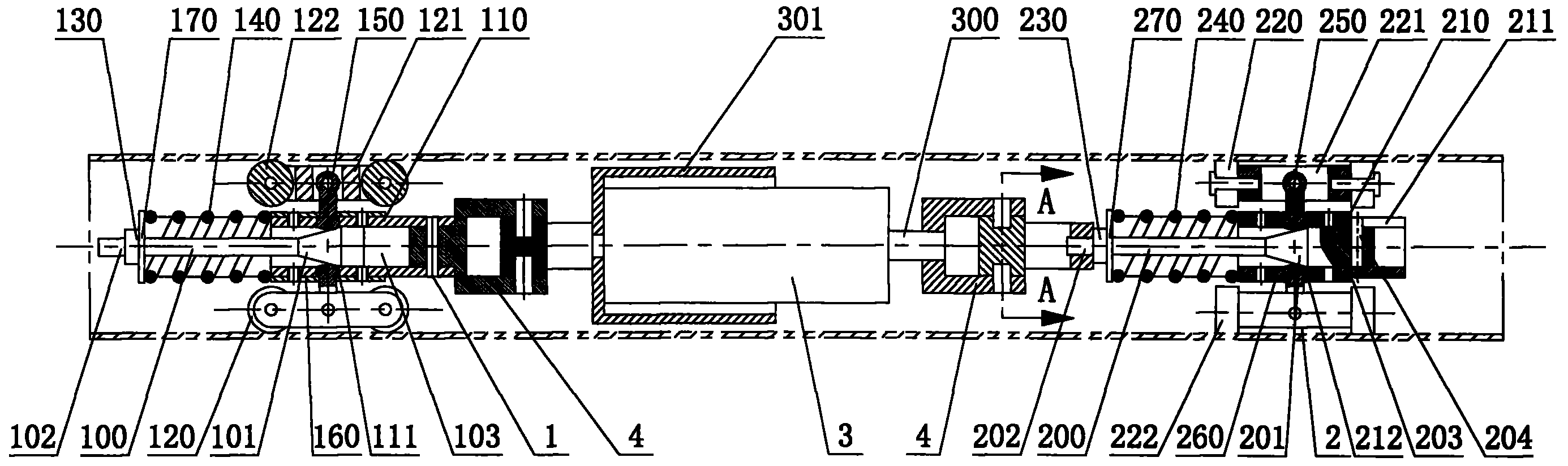
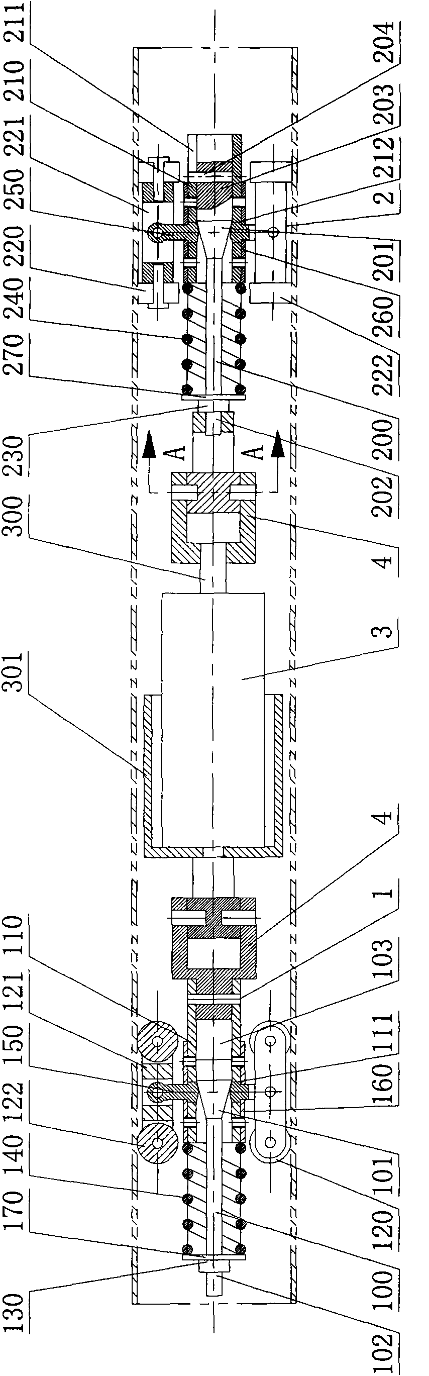
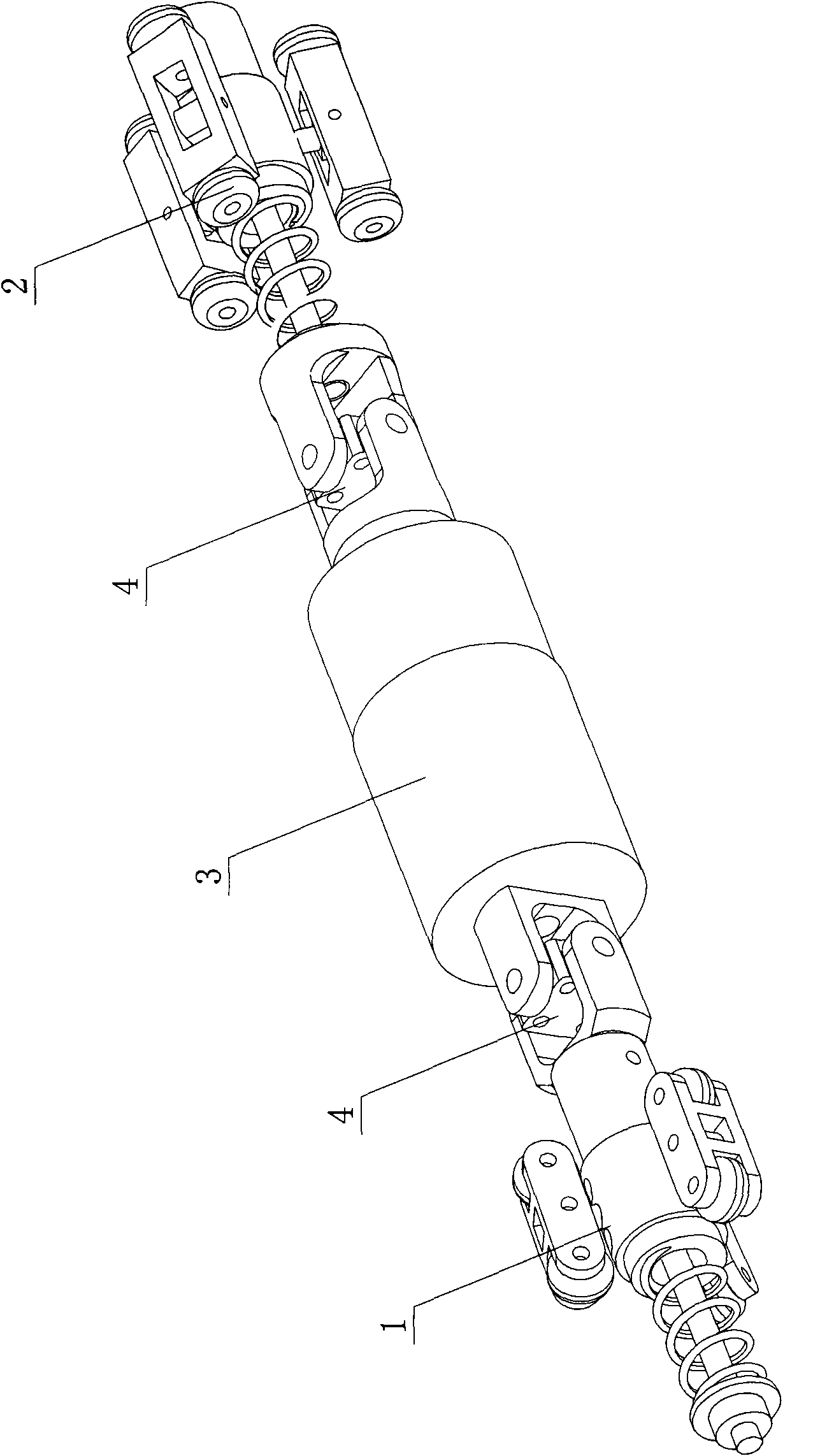
[0045] As shown in Fig. 1, Fig. 2 and Fig. 3, a kind of large traction force screw propulsion tiny pipe robot of the present invention comprises guide mechanism 1, screw propulsion mechanism 2 and rotary drive device 3, and rotary drive device 3 is located at guide mechanism 1 and Between the screw propulsion mechanism 2, in this embodiment, the guide mechanism 1 and the screw propulsion mechanism 2 are respectively connected to the rotary drive device 3 through a universal joint 4.

[0046] As shown in FIGS. 4 to 7 , the screw propulsion mechanism 2 includes a first tension rod 200 , a sleeve-shaped screw support 210 and at least three sets of screw wheels 220 uniformly arranged along the circumference of the screw support 210 . In this embodiment, three sets of spiral wheel sets 220 are provided. The spiral support 210 is provided with a chute 211 in the axial direction, and a first guide hole 212 corresponding to each spiral wheel set 220 is provided in the radial direction....


PUM


Abstract

The invention relates to a large traction screw propulsion micro-pipeline robot which comprises a guide mechanism, a screw propulsion mechanism and a rotary driving device arranged between the guide mechanism and the screw propulsion mechanism; wherein, the screw propulsion mechanism comprises a first tension rod, a spiral supporting seat and a spiral wheel set; a sliding groove is arranged at theupper edge of the spiral supporting seat along the axial direction, and a first guide hole is arranged along the radial direction of the spiral supporting seat; the spiral supporting seat is sheathedoutside the first tension rod which is formed by a first taper section, a first thread section and a first sliding bar section; the smaller diameter end of the first taper section is connected with the first thread section, and the bigger diameter end thereof is connected with the first sliding bar section; the first thread section is connected with the rotary driving device and provided with a first tension nut, a first compression spring is arranged between the first tension nut and the spiral supporting seat, the first sliding bar section is provided with a guide pin arranged inside the sliding groove, the spiral wheel set is connected with a spiral wheel set support pole, and the spiral wheel set support pole passes through the first guide hole and is contacted with the first taper section. The robot has the advantages of high load capacity, strong adaptive capacity for the pipe diameter change and better passing through capacity of a bent pipe.

Description

technical field [0001] The invention relates to a micro-pipeline robot, in particular to a micro-pipeline robot driven by a screw with a large traction force. Background technique [0002] In today's society, all kinds of tiny pipes (diameter less than 20mm) have been widely used in metallurgy, petroleum, chemical industry, military weaponry, nuclear power and other fields. Most of these tiny pipes are used in systems with very harsh working environments, which are prone to corrosion, fatigue damage, or potential defects to develop into cracks, which will cause leakage accidents and even cause heavy personnel and property losses, so they are used in these pipes In the process, it needs to be tested to ensure the safe, smooth and efficient operation of the pipeline system. However, the environment where tiny pipes are located is generally not directly accessible by humans, or direct intervention is not allowed, and due to the small inner diameter of the pipe and the intricat...

Claims


Application Information

Patent Timeline
Patent Type & Authority Patents(China)
IPC IPC(8): B25J7/00F17D5/02
Inventor 尚建忠罗自荣徐小军黑沫王晓明谢惠祥张祥坡
Owner NAT UNIV OF DEFENSE TECH
Why Eureka
Try Eureka