Line thermal printer

A thermal printer and line-type technology, applied in printing devices, printing, etc., can solve the problem of recording quality degradation and achieve the effect of preventing deterioration

Inactive Publication Date: 2009-10-28
ALPS ALPINE CO LTD
View PDF1 Cites 5 Cited by
  • Summary
  • Abstract
  • Description
  • Claims
  • Application Information

AI Technical Summary

Problems solved by technology

[0015] But, on recording paper 34, there are foreign matters such as dust, grain of sand or thermosensitive recording paper coating, and these foreign matters are hard things, so, if be swallowed by line type thermal head 33, just might make line type thermal head 33 swallow so. The type thermal head is damaged and the recording quality formed on the recording paper 34 is reduced.

Method used


Image

  • Line thermal printer
  • Line thermal printer

Examples


Embodiment Construction

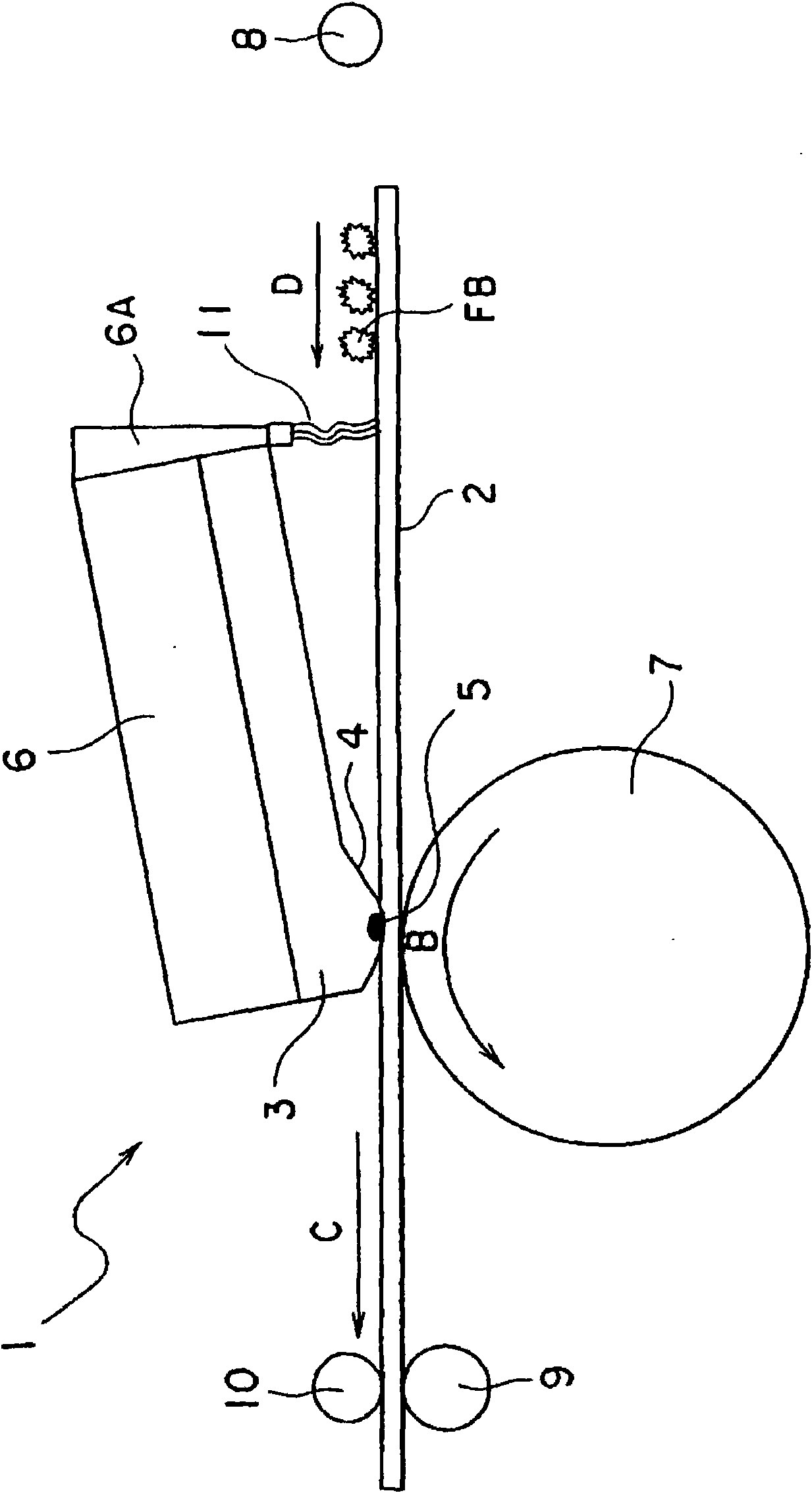
[0028] figure 1 Shows the main parts of the line thermal printer according to the present invention. A line thermal printer 1 according to the present invention has a line thermal head 3 that performs printing by selectively heating a plurality of heating elements that are driven by a recording paper 2 that is fed to the left in the figure. The entire area in the width direction is arranged so as to face each other, and heat can be selectively generated. On the line thermal head 3 is formed a protruding portion 4 protruding downward, and on the protruding portion 4 are arranged a plurality of heat generating elements 5, 5, . . . In addition, the recording paper in this embodiment is heat-sensitive recording paper.

[0029] Above-mentioned line type thermal head 3 is supported on the thermal head installation platform 6, line type thermal head 3 and thermal head installation platform 6 are centered on the rotation axis not shown in the figure by cam (not shown in the figure)...


PUM


Abstract

A line thermal printer includes a platen roller and a line thermal head including a plurality of heating elements. The heating elements are disposed to face the entire area of a recording sheet in a width direction of the recording sheet and selectively generate heat. The recording sheet is interposed between the platen roller and the line thermal head. The line thermal printer performs printing at the interposed position on the recording sheet by the selective generation of heat of the heating elements while the recording sheet is moved. The line thermal printer includes a foreign material blocking member. The foreign material blocking member is disposed upstream of the interposed position to come in contact with an upper surface of the recording sheet, and prevents foreign materials, which are placed on the upper surface of the recording sheet, from being moved toward the interposed position.

Description

technical field [0001] The present invention relates to a line thermal printer equipped with a line thermal head for printing by selectively heating a plurality of heat generating elements that are aligned with the entire area in the width direction of recording paper They are arranged in an opposing manner, and can selectively generate heat. The present invention particularly relates to a line thermal printer that prevents the line thermal head from swallowing foreign matter. Background technique [0002] The above-mentioned line thermal printer has been conventionally known (for example, refer to Patent Document 1). [0003] The following will refer to figure 2 The above-mentioned line thermal printer will be described. [0004] A platen roller 32 is arranged inside the frame 31 a , and a thermal line head 33 is arranged above the platen roller 32 . The recording paper 34 is conveyed between the line thermal head 33 and the platen roller 32 . [0005] Further, the line...

Claims


Application Information

Patent Timeline
Patent Type & Authority Applications(China)
IPC IPC(8): B41J2/32B41J2/335B41J11/00B41J29/17
CPCB41J2/325
Inventor 寺尾博年星野久山本寿之
Owner ALPS ALPINE CO LTD
Why Eureka
Try Eureka