Master-auxiliary vane pump and stator decompression method

A technology of vane and vane pumps, which is applied in the field of hydraulic pumps, can solve the problems of inconvenient maintenance, high working pressure and short service life of the vanes, and achieve the effects of convenient loading and unloading, low working pressure and long service life

Inactive Publication Date: 2009-10-28
NINGBO VICKS HYDRAULIC
View PDF2 Cites 14 Cited by
  • Summary
  • Abstract
  • Description
  • Claims
  • Application Information

AI Technical Summary

Problems solved by technology

[0004] In order to overcome the above-mentioned deficiencies, the object of the present invention is to provide the field with a dual vane pump and a stator decompres

Method used


Image

  • Master-auxiliary vane pump and stator decompression method
  • Master-auxiliary vane pump and stator decompression method
  • Master-auxiliary vane pump and stator decompression method

Examples


Embodiment Construction

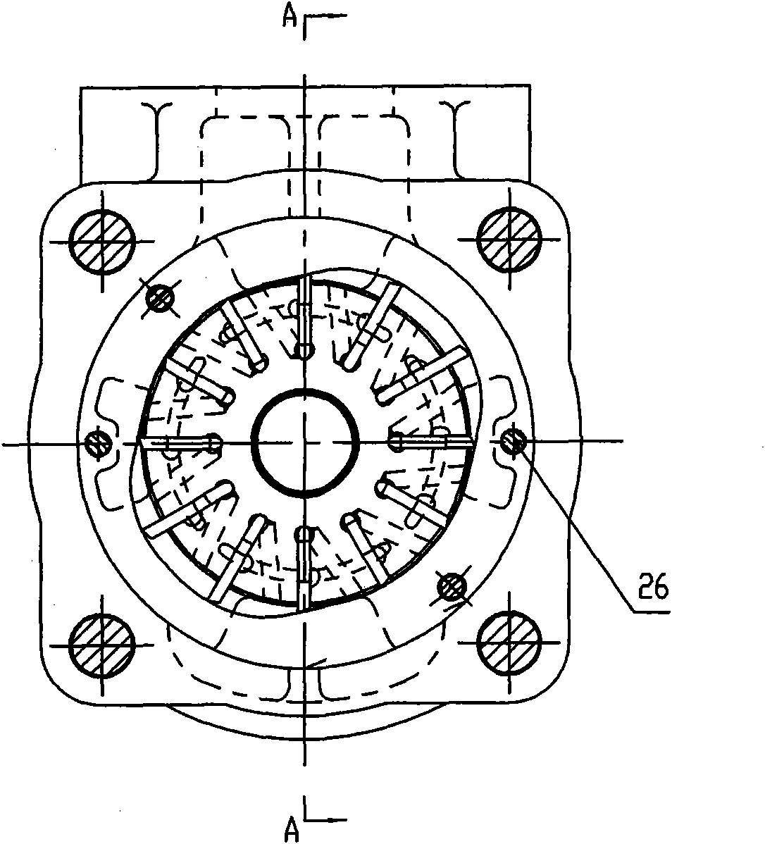
[0017] The embodiment takes the structure and working principle of the present invention as an example in conjunction with the drawings. Its structure is like image 3 , Figure 4 As shown, the front cover 16 and the rear cover 20 are connected to form a pump body, the front cover has a mounting flange surface connected to the oil pump support, and the front cover and the drive shaft are sealed with a skeleton oil seal 11. The rotor 2, the stator 3, and the daughter and mother blades 8 are clamped by screws 19 to form a pump core. The pump core and the front cover are plug-in structures, and the pump core is inserted into the pump through a pin 26. in vivo. The first PTFE retaining ring 14, the first O-ring 15, the second PTFE retaining ring 17, and the second O-ring 18 are respectively located between the front oil distribution pan and the front cover, and play a sealing role. The high and low pressure oil chambers in the pump body are separated. The transmission shaft is supporte...


PUM


Abstract

The invention relates to a master-auxiliary vane pump and a stator decompression method, being designed to solve the technical problems of the prior vane pump or master-auxiliary vane pump of inconvenient maintenance, large working pressure of vanes and short service life. The vane pump is characterized in that a second O-shaped ring is arranged at the joint of a front cover and a rear cover; a first O-shaped ring and a second polyfluortetraethylene retainer ring are arranged at the joint of a pump core and the front cover; the pump core is inserted in a pump body by a pin; a transmission shaft is supported in the pump body by a rolling bearing and a sliding bearing on a rear oil-distributing disc; and a front oil-distributing disc is in a taper shape and is in clearance fit with the front cover. In the stator decompression method, a middle pressure chamber is formed between the master vane and the auxiliary vane in a cavity between a rotor and a stator, and the width of the auxiliary vane is 1/3-1/4 of that of the master vane. The invention has simple structure, reasonable design, convenient maintenance, assembly and disassembly of the pump core, low working pressure of vanes, long service life, obvious effect of the decompression method and low pressing force of stators, thereby being suitable for transferring various fluids and improving like products.

Description

Technical field [0001] The invention relates to a hydraulic pump, which is a mother-child vane pump and a stator decompression method. Background technique [0002] At present, there are many hydraulic pump products on the market, which are generally divided into gear pumps, vane pumps and plunger pumps according to their structure. Among them, the vane in the rotor groove of the vane pump is in contact with the pump casing (stator ring), and the sucked liquid is pressed from the oil inlet side to the oil discharge side. For example, CN86203316U published in the Chinese Patent Literature, the announcement date June 11, 1987, the utility model name "high pressure vane pump", the vane pump with auxiliary valve, rated pressure above 200 bar, the pressure of the root of the blade in the suction zone can be The auxiliary valve can be easily adjusted at any time. Generally, it is only 4% to 6% of the working pressure. The pressure at the root of the blade at any angle within the range ...

Claims


Application Information

Patent Timeline
IPC IPC(8): F04C2/344F04C14/00
Inventor 孙国校叶玉堂郑尊刚
Owner NINGBO VICKS HYDRAULIC
Why Eureka
Try Eureka