Inflatable deploying solar wing capable of replacing panel in orbit

An inflatable deployment and battery panel technology, applied in the field of inflatable solar wings, can solve the problems of wasting materials, affecting the stability of the spacecraft, and threatening the life safety of astronauts, and achieving the effects of ensuring life safety, stable deployment process, and convenient replacement.

Inactive Publication Date: 2009-11-04
HARBIN INST OF TECH
View PDF1 Cites 8 Cited by
  • Summary
  • Abstract
  • Description
  • Claims
  • Application Information

AI Technical Summary

Problems solved by technology

[0003] The purpose of the present invention is to provide an inflatable solar wing that can replace the solar panel on the track, so as to solve the problem that the solar wing of the damaged or aging solar panel is repaired by the astronaut when the solar wing panel is damaged or aging during the orbital operation. The overall replacement not only poses a threat to the safety of astronauts, but also wastes materials and affects the stability of space vehicles.

Method used


Image

  • Inflatable deploying solar wing capable of replacing panel in orbit
  • Inflatable deploying solar wing capable of replacing panel in orbit
  • Inflatable deploying solar wing capable of replacing panel in orbit

Examples


specific Embodiment approach 1

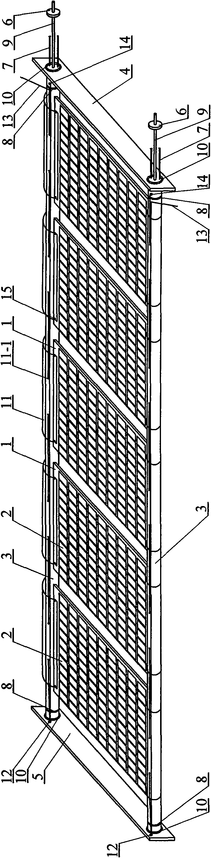
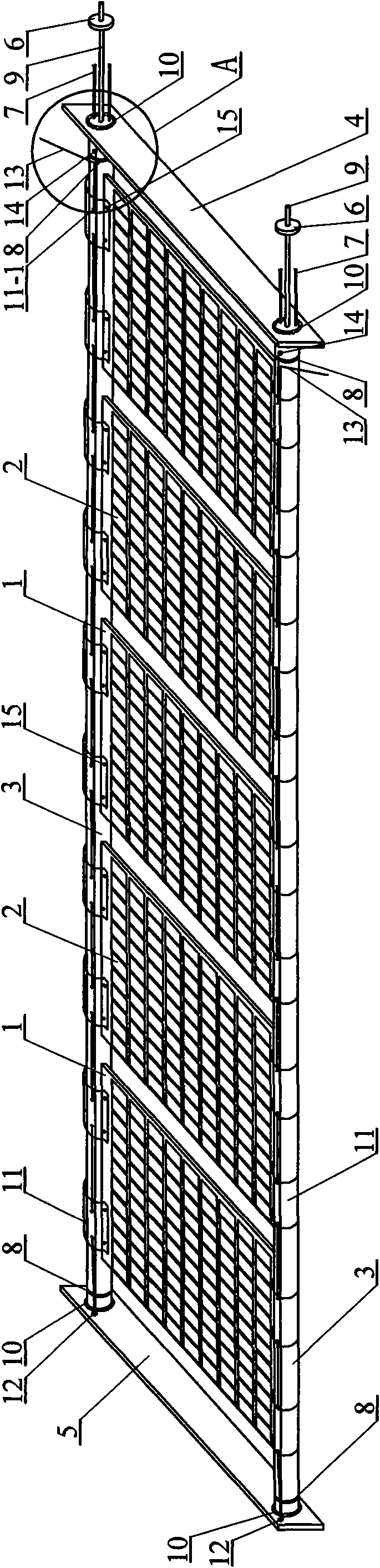
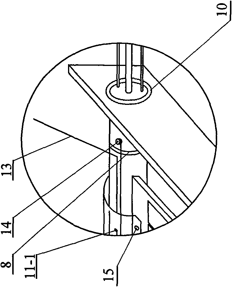
[0007] Specific implementation mode one: combine Figure 1 to Figure 4 Describe this embodiment. The solar wing described in this embodiment includes multiple battery substrates 1, multiple battery slices 2, two support tubes 3, a first horizontal plate 4, a second horizontal plate 5, two control valves 6, two A wire 7, four clamps 8, two inflation pipes 9 and four connecting plates 10; the two support tubes 3 are arranged in parallel, and the first horizontal plate 4 and the second horizontal plate 5 are respectively arranged on two supporting The two ends of the tube 3, the two ends of each supporting tube 3 are respectively inserted in the central hole of the corresponding connecting plate 10, the supporting tube 3 is closely matched with the central hole of the corresponding connecting plate 10, and each supporting tube 3 is connected to the first connecting plate 10 through the connecting plate 10. The two ends of the horizontal plate 4 and the second horizontal plate 5 a...

specific Embodiment approach 2

[0008] Specific implementation mode two: combination Figure 1 ~ Figure 3 To describe this embodiment, the split slip ring 11 in this embodiment is provided with two pull cord passing holes 11 - 1 . It is suitable for the situation that the split slip ring 11 has a large width and is convenient for pulling the split slip ring 11 . Others are the same as in the first embodiment.

specific Embodiment approach 3

[0009] Specific implementation mode three: combination figure 1 To illustrate this embodiment, the two ends of each battery substrate 1 in this embodiment are respectively installed in the opening of a split slip ring 11, which is suitable for the case where the split slip ring 11 has a large width and is easy to install. Others are the same as in the first or second embodiment.


PUM


Abstract

The invention relates to an inflatable deploying solar wing capable of replacing a panel in orbit, which relates to an inflatable deploying solar wing. The inflatable deploying solar panel solves the problems of material waste, poor aircraft stability and no guarantee for cosmonaut's life security existing in the process that the cosmonaut carries out whole replacement when the panel of the solar wing is damaged or ages in orbit. Two supporting tubes are fixedly connected with a first transverse plate and a second transverse plate through flanges; a cell baseplate is fixedly provided with cell slices, air filling pipes are communicated with the supporting tubes; wires are connected with the supporting tubes; each supporting tube is sleeved by an open slip ring; the cell baseplate is fixedly connected with the open slip ring; the second transverse plate is fixedly provided with two suspension links; the two flanges fixedly connected with the first transverse plate are respectively fixedly provided with a reel; and one end of a pull rope is wound on the reel, and the other end passes through the pull rope through holes in the suspension link and the open slip rings. The cell baseplate and the cell slices thereon can be conveniently replaced through the pull ropes, thereby ensuring cosmonaut's life security, reducing material waste and obtaining good spacecraft stability.

Description

technical field [0001] The invention relates to an inflatable and deployable solar wing, which belongs to the field of aerospace technology. Background technique [0002] Solar wings are the main form of power supply for space vehicles such as satellites, and are widely used in space vehicles such as satellites, manned spacecraft, and space stations. The space environment is extremely complex, high vacuum, strong ultraviolet rays, atomic oxygen, "cold black" and the existence of a large number of micro meteors and space debris, so that the solar wing's solar panel will be damaged or aging when it is in orbit. Make a replacement. The traditional method is for the astronauts to replace the solar wings with damaged or aging panels as a whole. In some cases, the damage is only a small part. The overall replacement will cause a waste of resources. In addition, the size of the solar wings is very large after deployment. Astronauts need to walk a long distance in the space enviro...

Claims


Application Information

Patent Timeline
Patent Type & Authority Applications(China)
IPC IPC(8): B64G1/44
Inventor 苗常青王友善肖丽波谭惠丰杜星文
Owner HARBIN INST OF TECH
Why Eureka
Try Eureka