Injection moulding method of membrane inside mould

A technology of injection molding and diaphragm, applied in the direction of coating, etc., can solve the problems of reduced product yield, poor rigidity of diaphragm F1, deviation of diaphragm F1, etc., to achieve the effect of improving yield

Inactive Publication Date: 2009-11-11
ASUSTEK COMPUTER INC
View PDF0 Cites 6 Cited by
  • Summary
  • Abstract
  • Description
  • Claims
  • Application Information

AI Technical Summary

Problems solved by technology

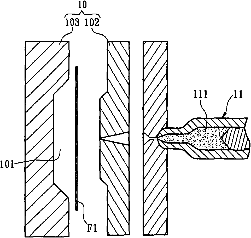
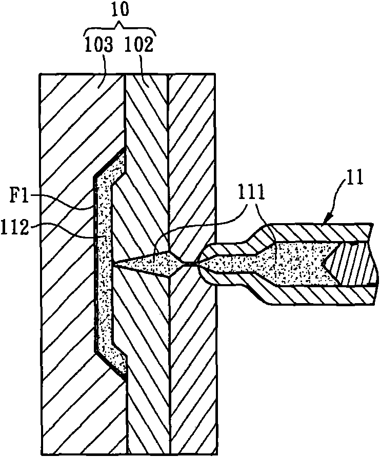
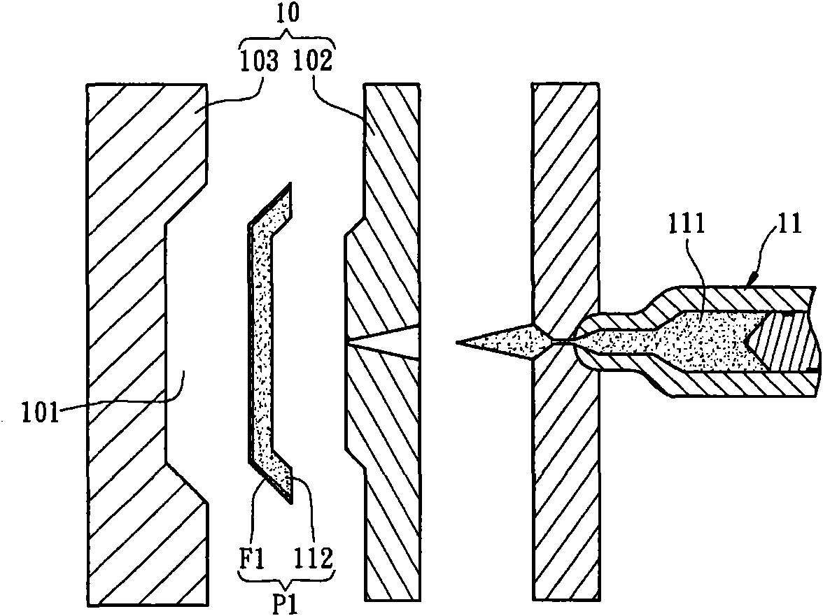
[0004] However, since the diaphragm F1 is in the shape of a flat plate, its rigidity is low, so that the pressure generated by the injection of the plastic 111 causes the diaphragm F1 to deviate, so figure 2 One side P11 of the molded product P1 shown, the membrane F1 protrudes from the base material 112 and is not aligned
In addition, due to the poor rigidity of the diaphragm F1, flashing is caused on the other side P12 of the molded product P1. Pass through the raised part of the diaphragm F1 and cover the diaphragm F1
Due to the deviation and overflow of the diaphragm F1, the yield rate of the product is greatly reduced, and the quality requirements cannot be met

Method used


Image

  • Injection moulding method of membrane inside mould
  • Injection moulding method of membrane inside mould
  • Injection moulding method of membrane inside mould

Examples


Embodiment Construction

[0012] A method and molded product of an in-mold film injection molding according to a preferred embodiment of the present invention will be described below with reference to related drawings, wherein the same components will be described with the same reference symbols.

[0013] image 3 It is a flow chart of a method for injection molding of an in-mold film (IMF) (hereinafter referred to as the molding method) according to a preferred embodiment of the present invention, which includes steps S01 to S06, Figure 4A to Figure 4D A schematic diagram of the molding method. Please refer to the following Figure 4A to Figure 4D and match image 3 To illustrate the molding method.

[0014] First, step S01 is to provide a film F2 with a predetermined pattern. The present invention does not limit the types of preset patterns, which can be changed according to actual needs. The predetermined pattern can be formed on at least one surface of the film F2, and can be formed on the su...


PUM


Abstract

The invention relates to an injection moulding method of a membrane inside a mould, comprising the following steps: correspondingly adjusting the shape of the membrane according to the shape of a mold cavity inside the mould; then correspondingly placing the membrane into the mold cavity; and finally ejecting a plastic to be moulded in the mould so that the membrane is closely jointed with the plastic.

Description

technical field [0001] The present invention relates to an injection molding method, in particular to an In-Molding Film (IMF) injection molding method. Background technique [0002] It is a widely used technology to mass-produce products by using injection molding (Injection Molding). Injection molding equipment can be used to quickly manufacture large quantities of plastic molded products, such as mobile phone casings or notebook computer casings. In addition, in order to make the product more beautiful, patterns can be formed on the product combined with the film, and there is the emergence of the In-Mold Film (IMF) injection molding technology. [0003] Figure 1A to Figure 1C It is a schematic diagram of a general in-mold diaphragm injection molding method. Such as Figure 1A As shown, a diaphragm F1 with a preset pattern is first placed in a mold cavity 101 of a mold 10. The mold 10 has a male mold 102 and a female mold 103, and the mold cavity 101 is combined by th...

Claims


Application Information

Patent Timeline
Patent Type & Authority Applications(China)
IPC IPC(8): B29C45/14B29C70/84
Inventor 荘文德李继良李吉丰
Owner ASUSTEK COMPUTER INC
Why Eureka
Try Eureka