Warp knitting machine

A technology of warp knitting machine and frame, which is applied in the field of warp knitting machine and can solve the problems of high cost and uneconomical

Inactive Publication Date: 2009-11-11
KARL MAYER TEXTILMASCHFAB GMBH
View PDF1 Cites 4 Cited by
  • Summary
  • Abstract
  • Description
  • Claims
  • Application Information

AI Technical Summary

Problems solved by technology

However, this solution is very uneconomical
In particular, this solution is very costly sin...

Method used


Image

  • Warp knitting machine
  • Warp knitting machine

Examples


Embodiment Construction

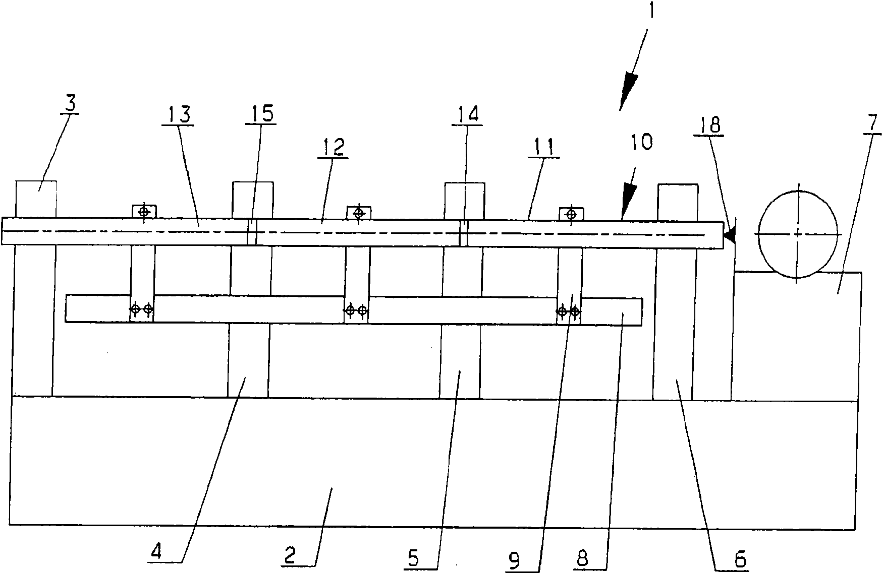
[0027] figure 1 A warp knitting machine 1 is shown very schematically, comprising a frame 2 with a plurality of supports 3-6. Here, the support plates 3 , 6 form the end-side end walls, and the support plates 4 , 5 form the intermediate plate. One end of the frame is provided with a jacquard drive 7 which is only schematically indicated.

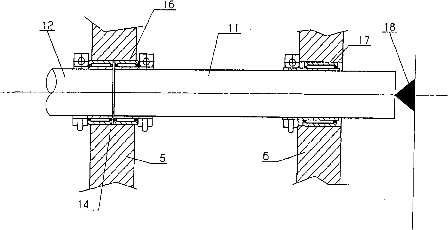
[0028] For example, the knitting tool bar 8 with guide needles, crochet needles, compound needles or other knitting tools is fixed on the support shaft 10 by the guide support rod 9 . If the support shaft 10 is rotated (a drive not shown in the figure is provided for this purpose), the guide support rod 9 is rotated and thus the looping tool bar 8 is moved in a reciprocating oscillating motion. If the looping tool bar 8 is designed as a bar, for example, the guide needles are guided through the interneedle gaps between the crochet needles during the described reciprocating oscillating movement. For this purpose, the guide rod 9 is connect...


PUM


Abstract

This invention relates to a warp knitting machine (1), including at least one loop-forming toolbar (8), on which several loop-forming tools are mounted. This is connected by levers (9) to a supporting shaft (10) which is divided into sections (11 - 13), wherein, each sections (11 - 13) is independently supported. Therefore the warp knitting machine has simply structure and simultaneously less sensitive to temperature affection.

Description

technical field [0001] The invention relates to a warp knitting machine comprising at least one knitting tool bar with a plurality of knitting tools connected to a support shaft by means of guide brackets. Background technique [0002] Such a warp knitting machine is known, for example, from DE 10 2004 023 802 B3. [0003] Knitting tool here refers to all elements that can participate in the knitting process of knitted fabrics, especially crochet needles, compound needles, thread guide or bar needles, chopping knives, etc. [0004] Warp knitting machines can have a working width of several meters. Even if the working width is large, the loop forming tools should still be arranged relatively closely adjacent to each other parallel to the width. In order to ensure that they work in sequence, different loop forming tools must work together more accurately. For example, comb needles must be able to swing through the gaps between the crochet needles without conflicting with th...

Claims


Application Information

Patent Timeline
IPC IPC(8): D04B27/00D04B27/24D04B35/30
CPCD04B35/30D04B27/00
Inventor K·B·布兰德尔
Owner KARL MAYER TEXTILMASCHFAB GMBH
Why Eureka
Try Eureka