
Rocket engine nozzle system

A rocket engine and nozzle technology, which is applied in the direction of rocket engine devices, engine manufacturing, engine components, etc., can solve the problems of discontinuity, inability to solve the flow at the outlet of the nozzle, and inability to optimize the space of the center body.

Inactive Publication Date: 2009-11-11
ARIANEGRP SAS
View PDF0 Cites 5 Cited by
  • Summary
  • Abstract
  • Description
  • Claims
  • Application Information

AI Technical Summary

Problems solved by technology

[0009] Such an arrangement can remedy some of the disadvantages of axially symmetric nozzles, however it does not optimize the space around the central body, nor does it solve the problem of flow discontinuities at the nozzle outlets at their inner edges

Method used


Image

  • Rocket engine nozzle system
  • Rocket engine nozzle system
  • Rocket engine nozzle system

Examples


Embodiment Construction

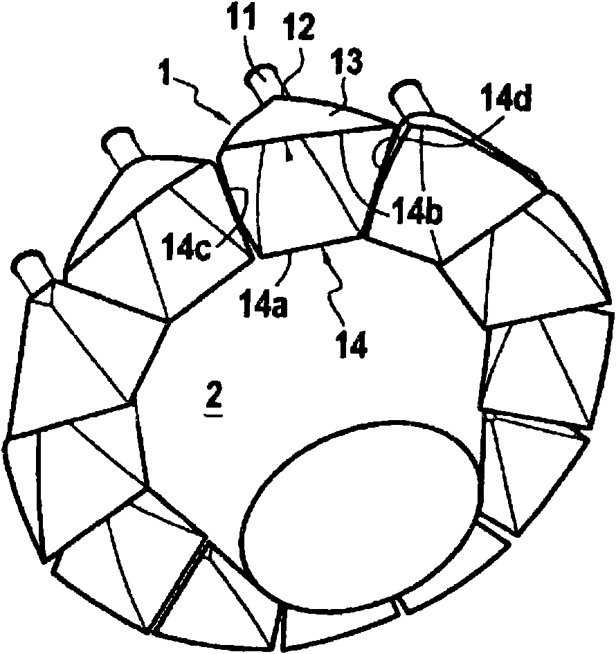
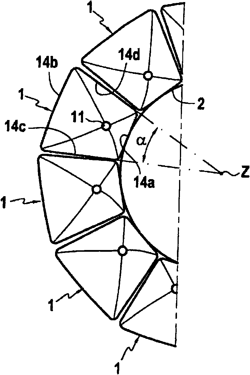
[0027] figure 1 is a general perspective view of a rocket motor nozzle system comprising a particular embodiment of the present invention comprising an axially symmetrical central body 2 of substantially frustoconical shape associated with a set of individual nozzles of asymmetrical shape In combination, said nozzles are arranged in an annular form around the central body, these individual nozzles are suitable to optimize the space they occupy and to avoid creating in the air flow where they leave the individual nozzles 1 to join to the outer side walls of the central nozzle 1 Discontinuity where gas from nozzle 1 expands along the wall.

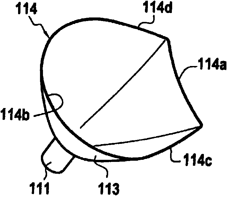
[0028] Each individual nozzle 1 has a circular nozzle throat 12 connected to the combustion chamber 11, and a diverging portion 13 terminating in a generally trapezoidal outlet portion 14, wherein each side 14a to 14d of the outlet portion may have some The particular shape, whether rectilinear or curved, depends on the constraints of the ...


PUM


Abstract

The rocket engine nozzle system comprises a set of individual nozzles distributed in a ring around a central core of axially symmetrical shape that presents a central axis. Each individual nozzle placed at the periphery of the central core comprises a circular section throat for receiving gas from a combustion chamber, and a diverging portion that is tangential to the central core. The diverging portion has an outlet section that presents first and second lateral sides that converge radially towards the central axis of the central core, a curved outer side having its convex side facing outwards, and an inner side situated in the vicinity of the central core.

Description

technical field [0001] The present invention relates to a rocket motor nozzle system, and more particularly to a nozzle system comprising a set of individual nozzles. Background technique [0002] Examples of rocket motor nozzle systems are already known, which use non-axisymmetric groups of nozzles of rectangular shape and mounted on a central body (also called plug). [0003] A rocket motor with a central body and a linear set of individual nozzles of this type has been proposed in particular by the supplier Rocketdyne according to the standard XRS-2000, suitable for fitting into a reusable single-stage launch in the case of the Lockeed-Martin X33 program device, the program is still in the project state. [0004] Figure 6 is a diagrammatic perspective view of such an XRS-2200 nozzle system, still in prototype state, having a linear central body 20 in combination with rows of non-axially symmetrical nozzles 10 of a rectangular outlet section. [0005] That type of rocket...

Claims


Application Information

Patent Timeline
Patent Type & Authority Applications(China)
IPC IPC(8): F02K9/60
CPCF05D2240/40F05D2250/322F05B2250/324F05D2250/324F05B2250/322F05D2250/13F05B2220/80F05B2250/13F02K9/97F05B2250/71F05D2250/71F05D2220/80F05B2240/40
Inventor D·维亚米R·加扎夫
Owner ARIANEGRP SAS
Learn More