Eureka AIR delivers breakthrough ideas for toughest innovation challenges, trusted by R&D personnel around the world.

Vehicle door mirror mounting structure

一种安装结构、后视镜的技术,应用在车辆部件、门、运输和包装等方向,能够解决妨碍观察等问题,达到提高美观、改善外观性、简化结构以及安装工序的效果

Inactive Publication Date: 2009-11-11
HONDA MOTOR CO LTD
View PDF2 Cites 12 Cited by
  • Summary
  • Abstract
  • Description
  • Claims
  • Application Information

AI Technical Summary

Problems solved by technology

Therefore, the door mirror mounting part and the mirror base may hinder the observation from the inside of the vehicle to the outside of the vehicle.

Method used


Image

  • Vehicle door mirror mounting structure
  • Vehicle door mirror mounting structure
  • Vehicle door mirror mounting structure

Examples


Embodiment Construction

[0044] Hereinafter, one embodiment of the present invention will be described based on the drawings. In addition, in the following description, unless otherwise specified, up and down and front and rear refer to up and down and front and rear in a vehicle body mounted state. In addition, in the figure, the arrow U points upward, the arrow D points downward, and the arrows O and I point to the outer side and the inner side of the vehicle respectively.

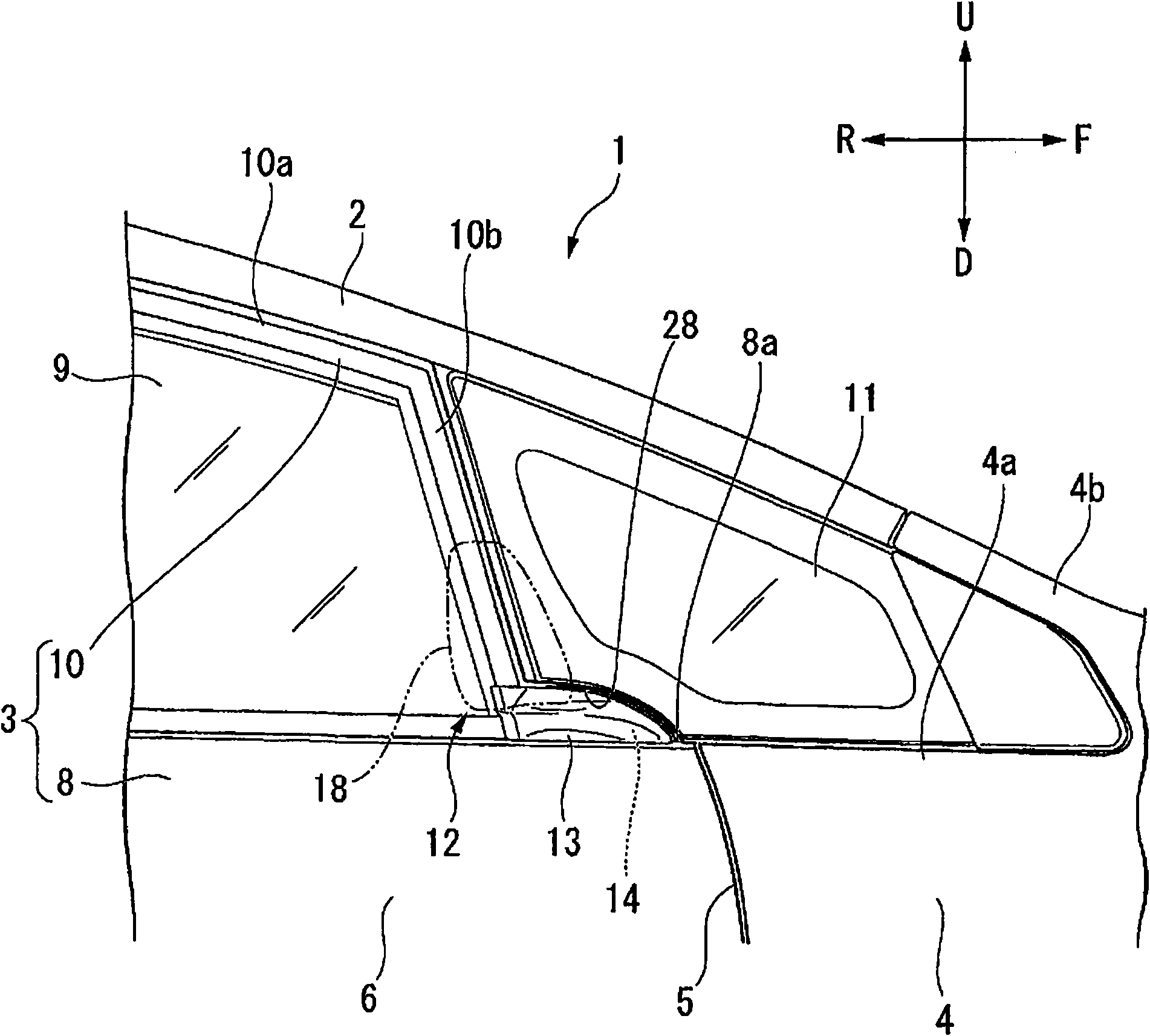
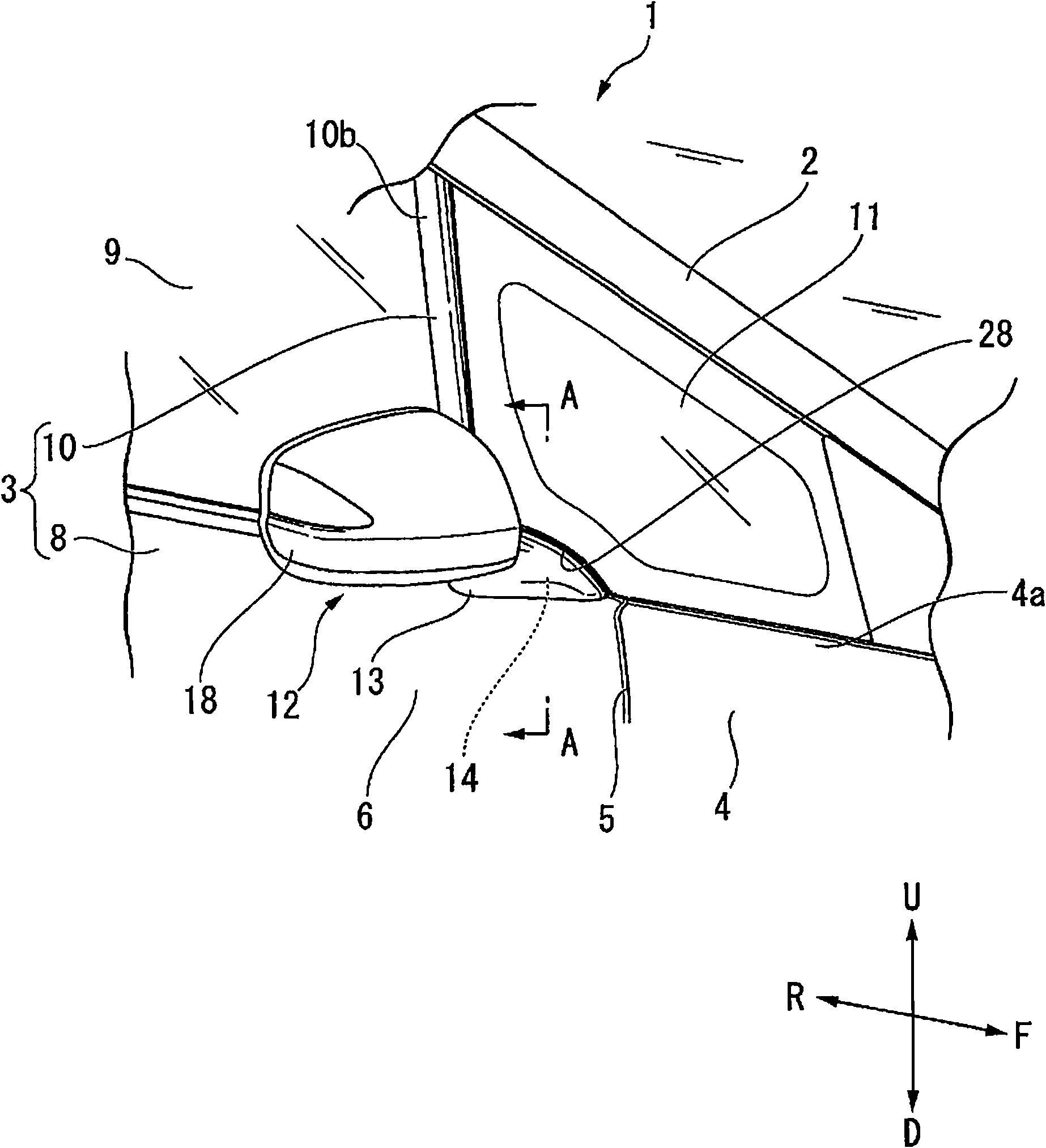
[0045] figure 1 , figure 2 A vehicle 1 employing the door mirror mounting structure of the present invention is shown. In these figures, 2 denotes a front pillar continuous with the roof of the vehicle, 3 denotes a side door, and 4 denotes a body side panel that forms a part of the periphery 5 on the front side of the door opening on the side of the vehicle body.

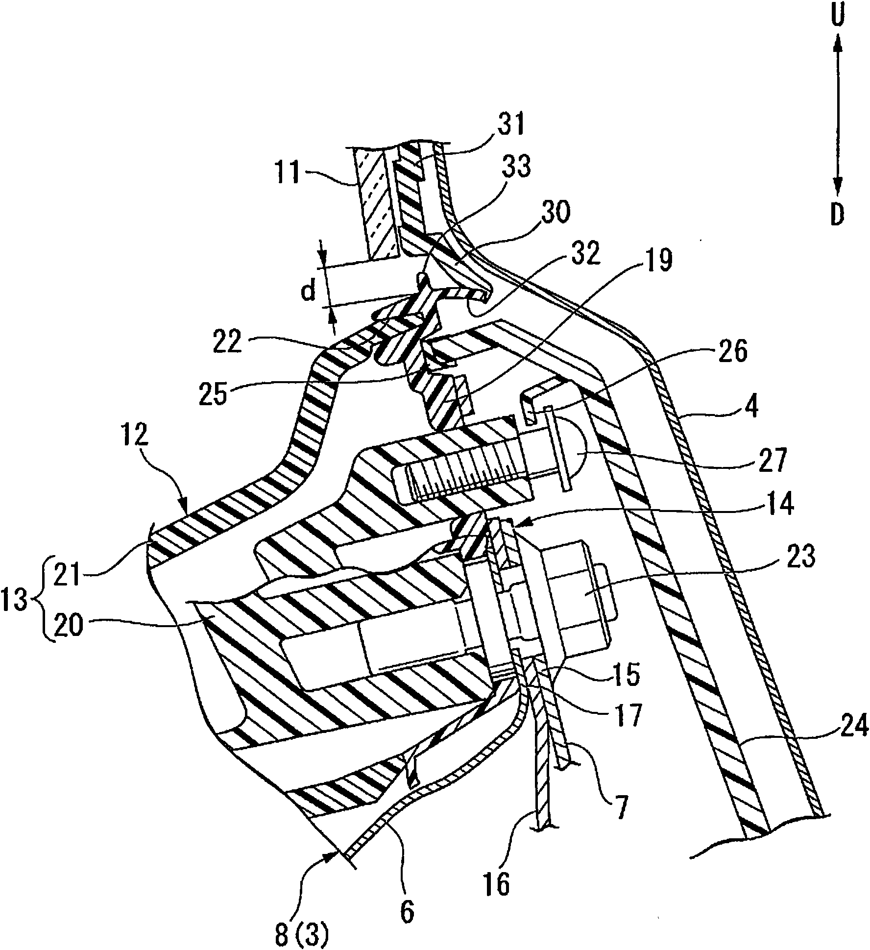
[0046] in addition, image 3 express with figure 2 The A-A section corresponds to the section. Figure 4 The disassembled state of the front part of the side ...


PUM


Abstract

A vehicle door mirror mounting structure for mounting a door mirror on a side door having a door body that includes an outer panel and an inner panel that are joined to each other, and also having a door sash that is provided at the upper part of the door body to form an outer frame. A door mirror installation section for installing the door mirror is provided at a position that is located at the upper side of the door body and in front of the door sash with respect to the front-rear direction of the vehicle.

Description

technical field [0001] The present invention relates to a mounting structure of a door mirror relative to a side door. [0002] This application claims priority based on Japanese Application No. 2007-269062 filed on October 16, 2007, the content of which is incorporated herein. Background technique [0003] There is known a vehicle in which a front corner glass is provided in a substantially triangular area on the front side of a front pillar in order to secure a view to the left and right front of the vehicle. In this type of vehicle, the front corner glass is fixedly arranged on the side of the vehicle body. [0004] As a door mirror mounting structure for such a vehicle, there is known a structure in which the width of the front edge of the door frame of the side door is set wider, and the door mirror is installed on the front edge of the wider door frame. part (refer to Patent Document 1). [0005] Patent Document 1: Japanese Patent Laid-Open No. 2004-217033 [0006]...

Claims


Application Information

Patent Timeline
Patent Type & Authority Applications(China)
IPC IPC(8): B60R1/06B60J5/04
CPCB60R1/06B60J5/0404
Inventor 大江知弘
Owner HONDA MOTOR CO LTD
Why Eureka
Eureka Blog
Learn More