Self-hydraulic automatic regulation valve

An automatic regulating valve, hydraulic technology, applied in the field of automatic regulating valve, self-hydraulic, can solve the problem of inability to realize automatic adjustment and so on

Active Publication Date: 2009-11-25
SHANDONG AOKE AUTOMATIC CONTROL EQUIP CO LTD
View PDF1 Cites 9 Cited by
  • Summary
  • Abstract
  • Description
  • Claims
  • Application Information

AI Technical Summary

Problems solved by technology

Although this kind of regulating valve has proposed certain measures under high pressure conditions, it must still be equipped with an actuator, which cannot realize automatic adjustment, and has not been used for a long time in actual working conditions.

Method used


Image

  • Self-hydraulic automatic regulation valve
  • Self-hydraulic automatic regulation valve

Examples


Embodiment Construction

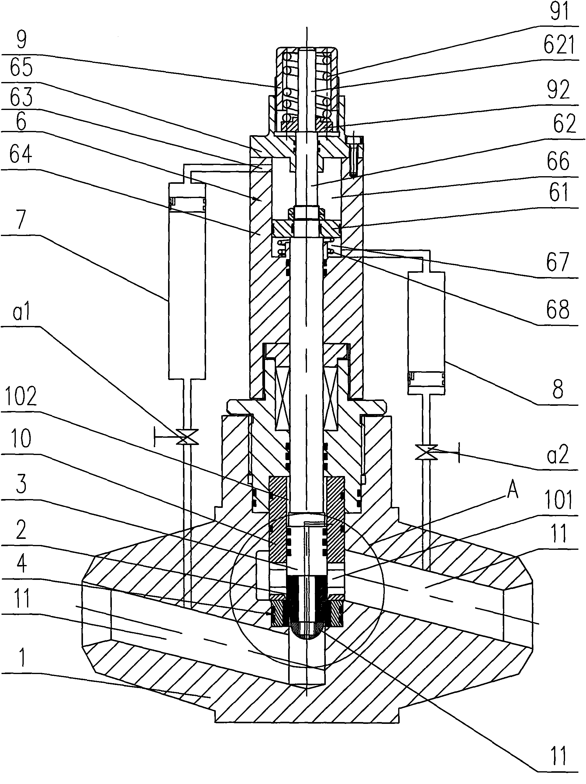
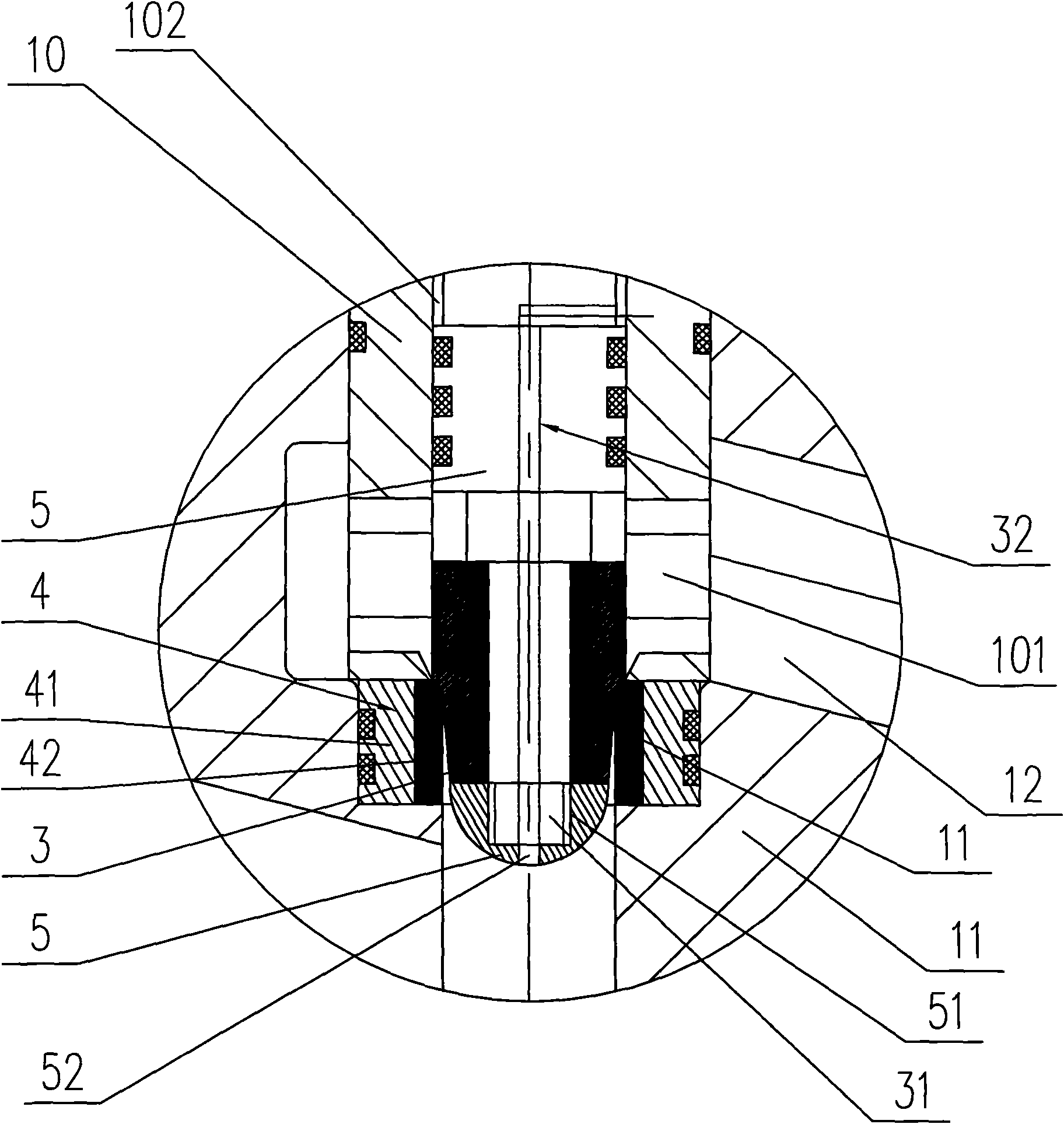
[0014] Such as figure 1 As shown, the specific embodiment of the present invention is a self-hydraulic, automatic regulating valve, including valve body 1, regulating head 2, regulating head fastener 5, main hydraulic cylinder 6, inlet hydraulic cylinder 7, outlet hydraulic cylinder 8, The valve stem 3 and the valve seat 4, wherein the valve body 1 is provided with two flow channels with different heights and heights, the water inlet flow channel 11 is set at the lower place, and the water outlet flow channel 12 is set at the higher place, and the two are connected through the middle flow channel . The valve seat 4 is arranged at the middle flow channel, and the regulating head 2 is set to form a sealing pair with the valve seat 4, and the mating surfaces of the regulating head 2 and the valve seat 4 are provided with slopes to form a sealing fit of the slopes. A main hydraulic cylinder 6 is arranged at the upper end of the valve rod 3, and the upper end of the valve rod 3 ex...


PUM


Abstract

This invention relates to a self-hydraulic automatic regulation valve, wherein upper end of a valve rod is set with a main hydraulic cylinder, and extends into main body of the main hydraulic cylinder to be fixedly connected with a piston; the piston divides the main body of the main hydraulic cylinder into an upper movable cavity and a lower movable cavity; left and right sides outside the valve body are respectively set with a charging hydraulic cylinder and a discharging hydraulic cylinder; lower end of the charging hydraulic cylinder is connected with one side of the charging flow channel, and upper end of the same is connected with liquid inlet of upper movable cavity in the main hydraulic cylinder; lower end of the discharging hydraulic cylinder is connected with one side of the discharging flow channel, and upper end of the same is connected with liquid inlet of the lower movable cavity in the main hydraulic cylinder. Accordingly, this invention regards the main hydraulic cylinder connected with charging flow channel and discharging flow channel at two ends of the valve body as the power source for pushing the piston therein to drive the valve rod to act, thereby realizing automatic switching-on, switching-off and regulation of regulation head.

Description

technical field [0001] The invention relates to a valve, in particular to a self-hydraulic and automatic regulating valve which realizes the automatic opening and closing of the valve by utilizing the pressure of the fluid medium itself in the pipeline. Background technique [0002] Existing control valves, such as single-seat control valves and sleeve control valves, must be equipped with pneumatic or electric actuators to achieve the set adjustment requirements, and cannot work safely and normally under high-pressure conditions. Check the Chinese patent database, the authorized announcement number is: CN2721992, and the utility model patent named "High Pressure Differential Regulating Valve" discloses the following content: "The utility model relates to a high pressure differential regulating valve. The structure includes a valve body and a valve seat. , valve stem, bonnet, throttling parts, actuators, seals and mounting parts, the throttling parts are fixedly connected to...

Claims


Application Information

Patent Timeline
Patent Type & Authority Applications(China)
IPC IPC(8): F16K17/00F16K1/00F16K31/122
Inventor 林文华叶建中林博策
Owner SHANDONG AOKE AUTOMATIC CONTROL EQUIP CO LTD
Why Eureka
Try Eureka