
Method for controlling car light irradiation distance by a convex lens moving apparatus

A technology of moving device and irradiation distance, which is applied to the components of lighting devices, signal devices, lighting devices, etc., which can solve the problems of light scattering, loss of concentrated light, and unclear explanation of technical solutions, so as to meet visual requirements and save energy. resource effect

Inactive Publication Date: 2009-11-25
DALIAN HUIHUA TECH
View PDF1 Cites 4 Cited by
  • Summary
  • Abstract
  • Description
  • Claims
  • Application Information

AI Technical Summary

Problems solved by technology

Although the description of the patent application is simple, the explanation of the technical solution is not very clear. The light emitted by the lamp located in the bushing will first undergo a series of complex reflections in the bushing. After being refracted by the lens, the phenomenon of concentrated light loss will occur
That is, the irradiated light will be scattered, the beam of light cannot be gathered and the brightness is not strong, so it is not suitable for vehicles to drive at night

Method used


Image

  • Method for controlling car light irradiation distance by a convex lens moving apparatus
  • Method for controlling car light irradiation distance by a convex lens moving apparatus
  • Method for controlling car light irradiation distance by a convex lens moving apparatus

Examples


Embodiment Construction

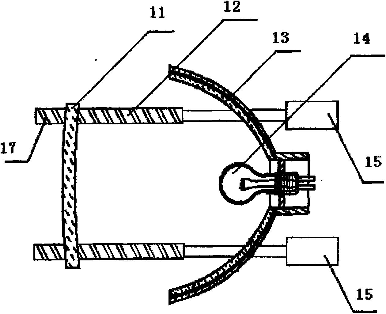
[0030] Combine below Figure 1 to Figure 6 , the present invention is further described:

[0031] The method of the invention relates to a control method of a convex lens moving device of a car lamp.

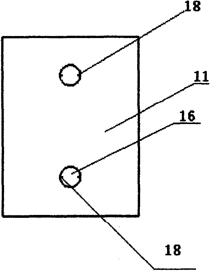
[0032] Such as figure 1 Shown, this convex lens moving device comprises driving device and interlocking device, and interlocking device is transmission guide rod 12, and driving device is micromotor 15; Transmission guide rod 12 is provided with spiral chute 17, and one end of transmission guide rod 12 passes The reflector surface 13 of the passing light passes through the passage hole 16 on the convex lens sheet 11; the micro motor 15 is connected with any one end of the transmission guide rod 12. There are two transmission guide rods 12, and each transmission guide rod 12 ends are respectively provided with a micro motor 15.

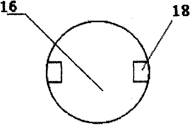
[0033] Such as figure 2 and image 3 As shown, two or more protrusions 18 that can slide in the spiral chute 17 are provided on the edge of the pa...


PUM


Abstract

A method for controlling car light irradiation distance by a convex lens moving apparatus, which changes the distance between the car light and the convex lens according to the car speed by a convex lens moving apparatus, thereby, realizes the direct ratio relation of the car speed and the car light irradiation distance. The invention can enable the car light irradiation range to be controlled more freely, and can be arranged in different steps for satisfying the demands of different people; also can save one car light arrangement.

Description

technical field [0001] The invention relates to a method for controlling the irradiation distance of a motor vehicle lamp, in particular to a method for controlling the irradiation distance of a vehicle lamp through a convex lens moving device. Background technique [0002] In the prior art, an automobile headlight lighting system is usually provided with two lighting lamps according to functions: a long-distance light and a short-distance light. The long-distance light and the short-distance light are usually designed in advance, so when the distance between the car light and the lens and the curvature of the reflector do not change, the lighting distance and brightness of the two lights are determined. unchangeable. [0003] This limitation creates drawbacks for practical applications. For example: the driver is driving on the highway at night, because there are not many vehicles, the reaction of the driver will slow down after a long time. Therefore, headlights will pl...

Claims


Application Information

Patent Timeline
Patent Type & Authority Applications(China)
IPC IPC(8): F21S8/10F21V14/06F21V17/00H05B37/02B60Q1/06F21W101/10
Inventor 涂萧恺
Owner DALIAN HUIHUA TECH
Learn More