Fuel cell based on in-plate counter-flow flow field

A fuel cell, countercurrent technology, applied in the direction of fuel cells, fuel cell additives, fuel cell grouping, etc., can solve the problems of concentration drop, concentration difference, uneven current density distribution, etc., to overcome the gradual increase or decrease , to promote the effect of uniform distribution

Active Publication Date: 2011-06-15
TSINGHUA UNIV
View PDF2 Cites 1 Cited by
  • Summary
  • Abstract
  • Description
  • Claims
  • Application Information

AI Technical Summary

Problems solved by technology

All current fluid configuration schemes (including the above-mentioned ones) have a common advantage, that is, the configuration of the flow channel is simple, and the fluid flows from the inlet to the outlet in parallel and unidirectionally in the flow channel, but they also have a common disadvantage, that is, those involved in the reaction The unidirectional flow of the fluid will cause the concentration of each component of the fluid to decrease monotonously (for reactants) or increase monotonically (for products) from the inlet to the outlet, resulting in the concentration of each component of the fluid in the active area of ​​the battery. The concentration in each micro-area is not the same, which eventually becomes an important reason for the uneven distribution of current density in the entire active area.

Method used


Image

  • Fuel cell based on in-plate counter-flow flow field
  • Fuel cell based on in-plate counter-flow flow field
  • Fuel cell based on in-plate counter-flow flow field

Examples


Embodiment Construction

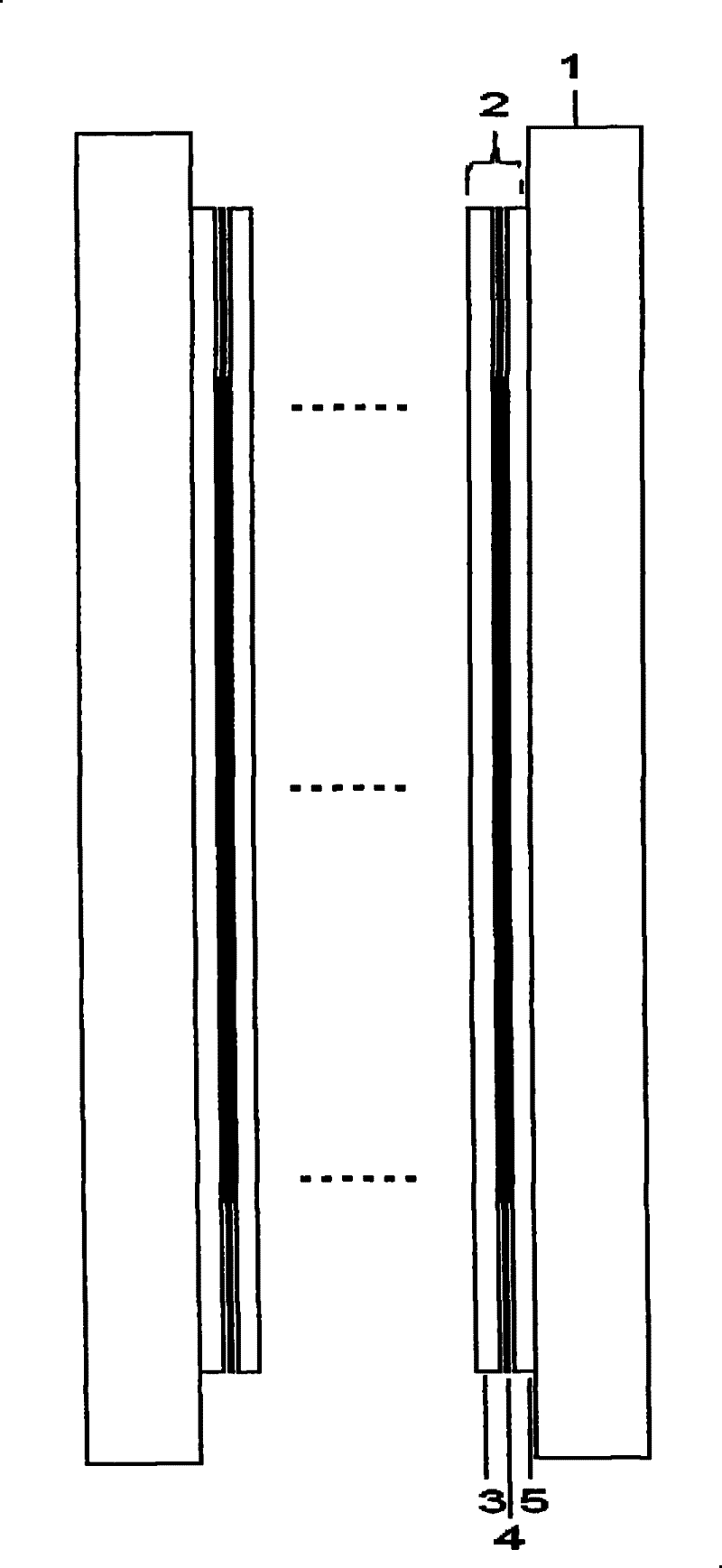
[0015] The fuel cell based on the countercurrent flow field in the plate proposed by the present invention has a structure such as figure 1 As shown, it includes a splint 1 and a plurality of battery cells 2 , and the plurality of battery cells 2 are sandwiched between two splints 1 after being connected in series. The battery unit 2 includes an air flow field plate 3 , a fuel flow field plate 5 and a membrane electrode 4 , and the air flow field plate 3 and the fuel flow field plate 5 are respectively placed on both sides of the membrane electrode 3 .

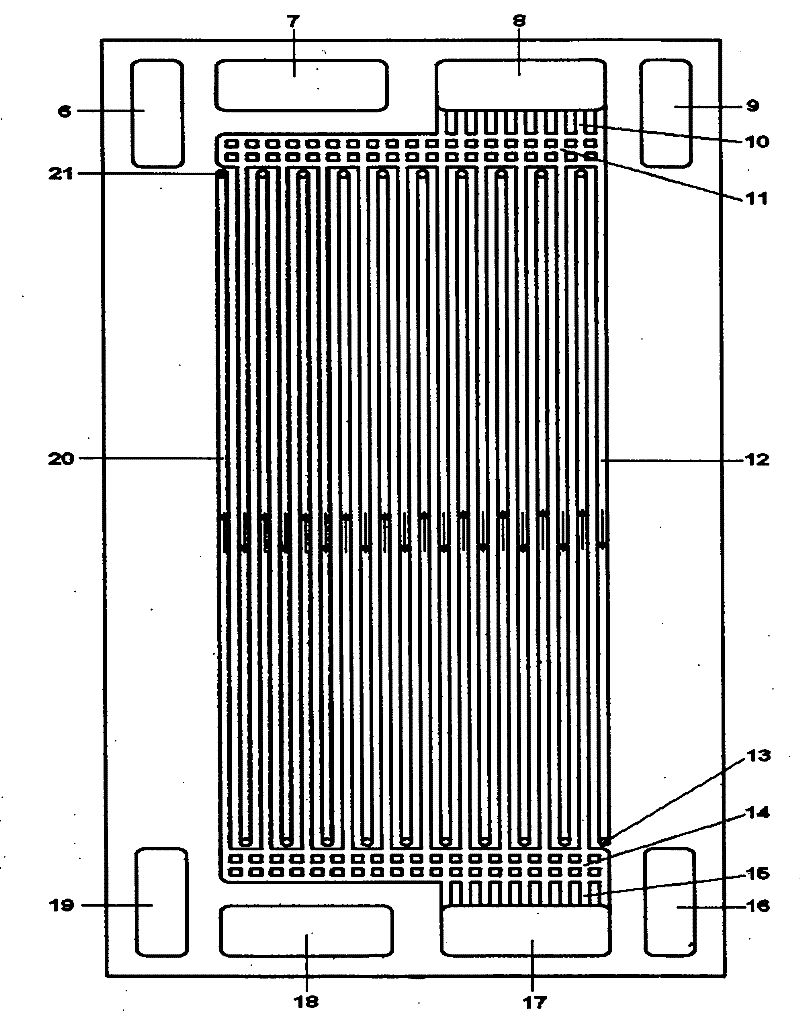
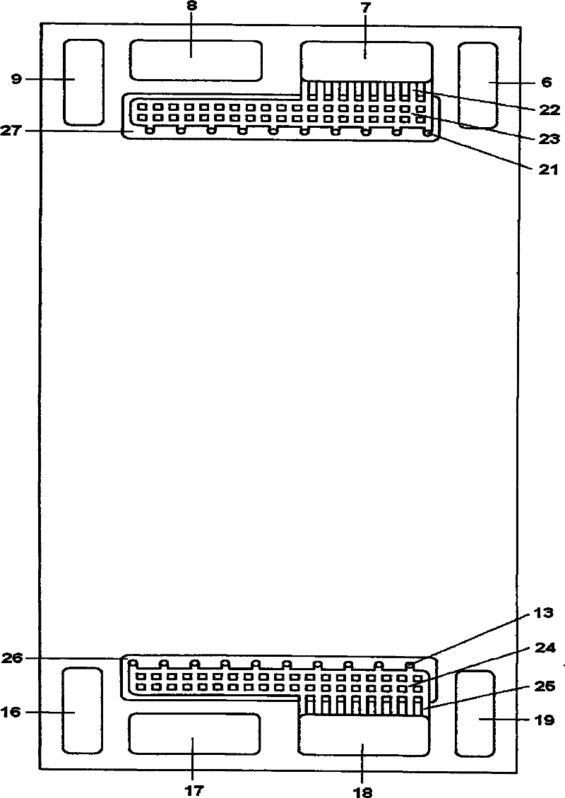
[0016] The structure of the above-mentioned air flow field plate 3 is as follows: figure 2 As shown, the first fuel inlet 6, the second air outlet 7, the first air inlet 8 and the second fuel outlet 9 are sequentially opened on the upper end from left to right, and the second group of air flow field plates are opened on the lower side. The air passes through the hole 21 . The lower end of the air flow field plate is provide...


PUM


Abstract

The present invention relates to a fuel cell based on the in-plate counter-flow flow field and belongs to the technical field of fuel cell. The air flow field plate of the cell unit is provided with two pairs of air ports, two groups of air flow channels with are distributed separately with each other and two groups of air through-holes which pass through the air flow field plate thereby forming the inner counter-flow flow field of the air plate. The air flow field plate is also provided with two pairs of fuel ports, two groups of fuel flow passages which are arranged separately and two groupsof fuel through-holes which pass through the fuel flow field plate thereby forming the inner couter-flow flow field of the fuel plate. The air flow field plate is also provided with two pairs of fuelports which are provided with two pairs of air ports thereby realizing the integration of two flow field plates. In the fuel cell of the invention, the gradual reduction of the concentration of eachcomponent of the fluid in one flow passage is averaged by the gradual increase of the concentration of each component of the fluid in the adjacent flow passage thereby realizing that the concentrationof each component in the fluid is kept same basically in any macroscopic micro cells in the whole active region.

Description

technical field [0001] The invention relates to a fuel cell based on a countercurrent flow field in a plate, belonging to the technical field of fuel cells. Background technique [0002] Among the flow channel configuration schemes in the known fuel cell bipolar plate stack design, typical configurations include serpentine configuration, parallel configuration, intersecting comb configuration, dot configuration and porous body configuration. In the serpentine configuration scheme, as reported in U.S. Patent No. 4,631,239 (1986), the fluid arrives at the outlet from the inlet through a plurality of tortuous flow passages side by side; in the parallel configuration scheme, as reported in US Patent No. 4,631,239 (1986) , the fluid reaches the outlet from the inlet through multiple straight flow channels side by side; A plurality of flow passages, through the porous diffusion layer and the reactant layer under the ridge, then through a plurality of flow passages side by side, f...

Claims


Application Information

Patent Timeline
Patent Type & Authority Patents(China)
IPC IPC(8): H01M4/86H01M8/04H01M8/24H01M8/02H01M8/0258H01M8/04089H01M8/241H01M8/2457H01M8/2465
CPCY02E60/50
Inventor 张红飞裴普成袁星
Owner TSINGHUA UNIV
Why Eureka
Try Eureka