Electromagnetic shield door

An electromagnetic shielding door and shielding body technology, which is applied in the direction of defense against harmful radiation, etc., can solve the problems of high shielding efficiency, operator inconvenience, and increased insertion resistance, and achieve high shielding efficiency, easy opening and closing, and insertion resistance. small effect

Inactive Publication Date: 2009-12-02
安方高科信息安全技术(北京)有限公司
View PDF0 Cites 4 Cited by
  • Summary
  • Abstract
  • Description
  • Claims
  • Application Information

AI Technical Summary

Problems solved by technology

However, no matter which type it is, there is always a fit gap between the various components of the shielding structure (for example, between the door knife and the beryllium copper reed, between the door knife and the shielding gasket), and it has no effect on electromagnetic shielding. There are also requirements for the complexity of the door, so it is difficult to achieve high shielding effectiveness through limited structural combinations, and usually only meet the B-level requirements in the national confidentiality standard GGBB1-1999
[0003] In addition, there is also the purpose of reducing electromagnetic leakage by pressing the shielding members against each other, thereby reducing the fit gap, such as figure 1 As shown, such an electromagnetic shielding door includes a bracket 20 and a door knife 10, and the door knife 10 installed on the door (not shown) is inserted between the beryllium copper reeds 21, 23 of the bracket 20 (installed on the shielding body). The beryllium copper reeds 21 and 23 are respectively inserted into the rod-shaped shielding gaskets 22 and 24 in advance. Since the shielding gaskets 22 and 24 are elastic, when the door knife is inserted into the beryllium copper reeds, it will move toward the beryllium copper reeds. The bias pressure makes the beryllium copper reed more close to the door knife, so that the fit gap between them is greatly reduced, which effectively prevents the leakage of electromagnetic waves and improves the shielding effectiveness. However, it also increases the insertion resistance. This will make it difficult to close and open the screen door, which will bring great inconvenience to the operator

Method used


Image

  • Electromagnetic shield door
  • Electromagnetic shield door
  • Electromagnetic shield door

Examples


Embodiment Construction

[0024] Embodiments of the electromagnetic shielding door according to the present invention will be described in detail below with reference to the accompanying drawings. In the following, "outer" and "inner" are relative to the shielding body, the part closer to the shielding body is called "inner", and vice versa is called "outer".

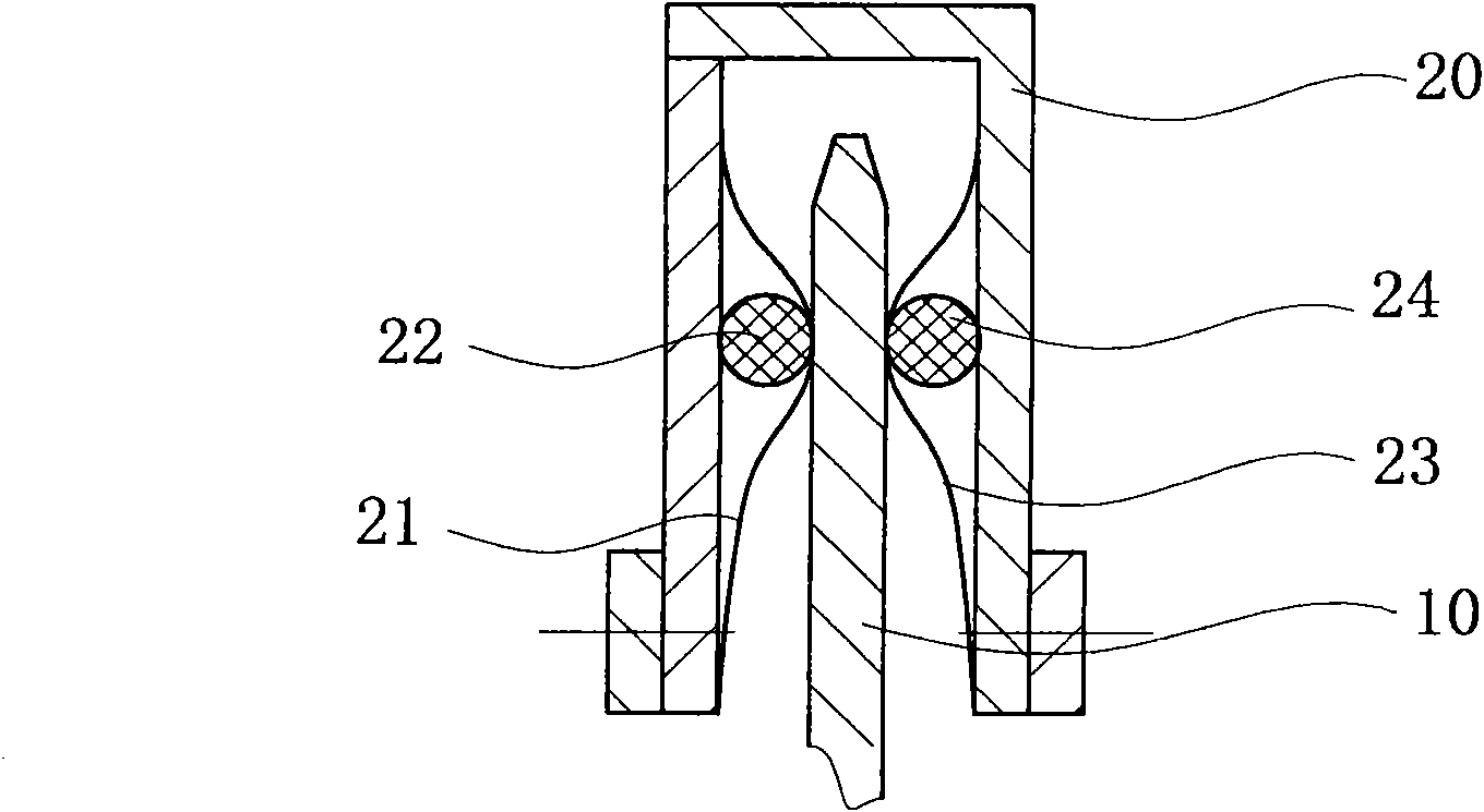
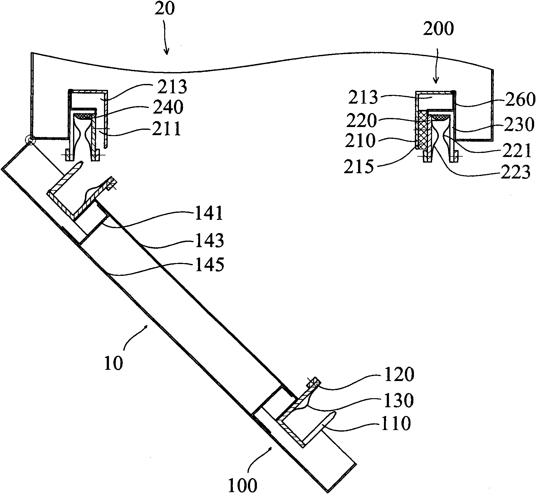
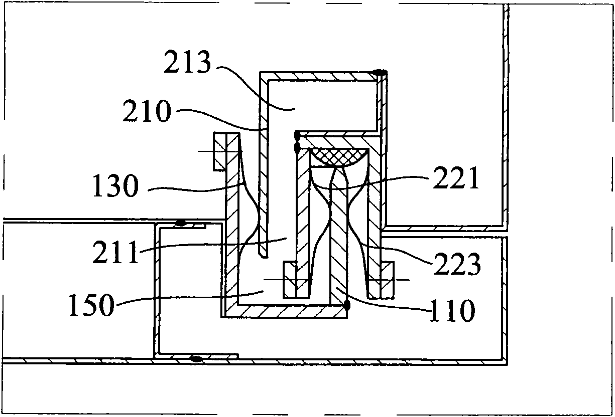
[0025] figure 2 is a schematic diagram of an electromagnetic shielding door according to an embodiment of the present invention, wherein the door is in an open state. In order to prevent the electromagnetic wave in the shield from leaking from the door gap, a plug-in 100 is arranged around the edge of the door body 10. Correspondingly, a socket 200 is provided at the edge of the shield 20. When the door is closed, the plug-in 100 is inserted into the socket 200, thereby Seal the door gap to achieve electromagnetic shielding effect. The structure of the plug-in 100 and the socket 200 will be described in detail below. Since the plug-in and soc...


PUM


Abstract

The invention discloses an electromagnetic shield door, comprising a plug-in (100) which is fixed onto a door and a socket (200) which is fixed onto a shield, wherein, the plug-in comprises a door knife (110), a door bracket (120) and a metal reed (130) which is arranged on the door bracket; the socket comprises an inner slotting tool (210), a middle bracket (220) and an outer bracket (230), the middle bracket and the outer bracket are arranged with metal reeds (221, 223) which are relatively depended, a by-pass channel (211) is formed between the middle bracket and the inner bracket, a chamber (213) is arranged at the end part of the channel; wherein, the door knife (110) is inserted into the metal reeds (221, 223) which are arranged between the middle and outer brackets and are relatively depended when the door is closed, the inner side of the inner slotting tool (210) is closely contacted with the metal reeds of the door bracket, therefore, the door is easily opened and closed while obtaining relatively high shielding effectiveness.

Description

technical field [0001] The invention relates to an electromagnetic shielding door on an electromagnetic shielding device. Background technique [0002] Electromagnetic shielding doors are used on shielding bodies such as electromagnetic shielding boxes and shielding cabinets to seal the openings on the shielding body and prevent electromagnetic waves from leaking out. At present, electromagnetic shielding doors are roughly divided into three types. The first type is the structure in which the door knife and the beryllium copper reed are in close contact. The second type is the structure in which the door knife, bracket or the like is pressed against the shielding liner. Structure, there is also a combination of the above two structures, such as the "protective equipment door seam electric sealing structure" disclosed by the notification number CN2549145, which is exactly this type. In this type of combination, electromagnetic waves are sealed by various shielding structures...

Claims


Application Information

Patent Timeline
Patent Type & Authority Applications(China)
IPC IPC(8): E06B5/18
Inventor 郭林朱安东房非拉于泳王冰
Owner 安方高科信息安全技术(北京)有限公司
Why Eureka
Try Eureka