Eureka AIR delivers breakthrough ideas for toughest innovation challenges, trusted by R&D personnel around the world.

Mechanical elastic large-angle slewing limit mechanism

A limit mechanism, large-angle technology, applied in the direction of mechanical equipment, position/direction control, non-electric variable control, etc., can solve problems such as limited range of rotation angle, equipment impact, affecting normal operation of equipment, etc., to achieve a wide range of applications, Avoid the effect of shock

Active Publication Date: 2011-05-25
CHINA NORTH IND NO 205 RES INST
View PDF2 Cites 0 Cited by
  • Summary
  • Abstract
  • Description
  • Claims
  • Application Information

AI Technical Summary

Problems solved by technology

[0003] The technical problem to be solved by the present invention is to overcome the problems of low reliability of the existing electromechanical rotary limit mechanism, the limited range of rotation angle satisfied by the mechanical limit mechanism, and the large impact caused by rigid collision on the equipment, which affects the normal operation of the equipment, etc. Provide a mechanical flexible large-angle rotary limit mechanism that can protect equipment components and wires

Method used


Image

  • Mechanical elastic large-angle slewing limit mechanism
  • Mechanical elastic large-angle slewing limit mechanism
  • Mechanical elastic large-angle slewing limit mechanism

Examples


Embodiment Construction

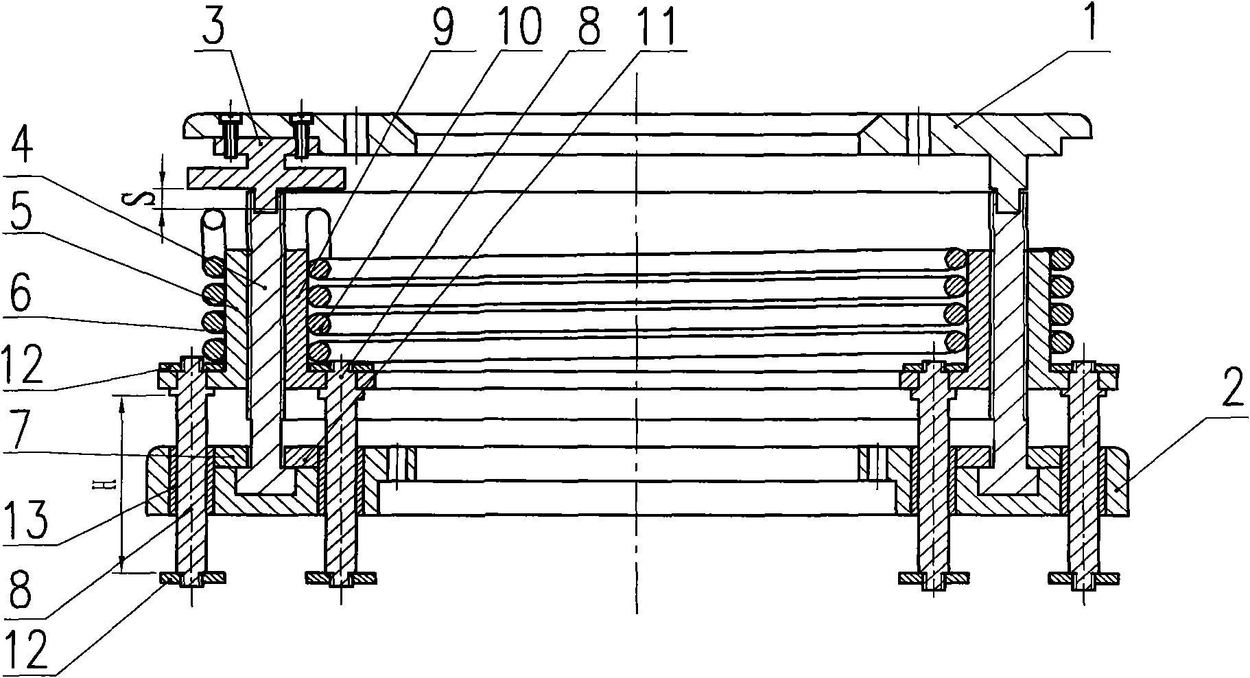
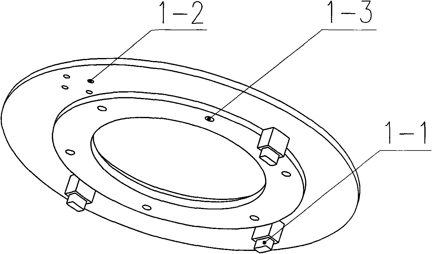
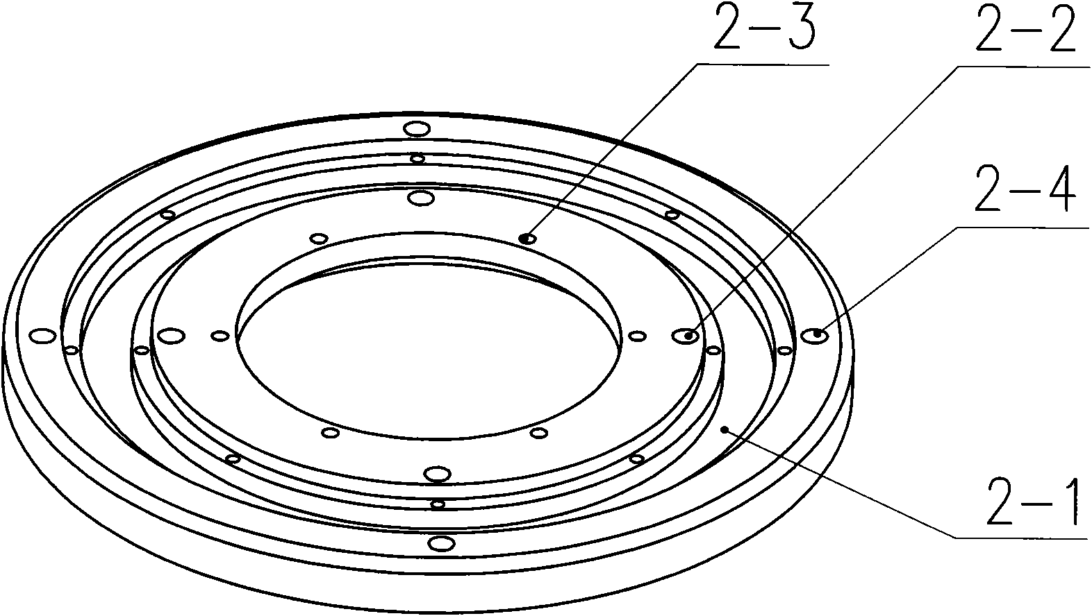
[0020] as figure 1 As shown, the large-angle rotation limit mechanism of the preferred embodiment of the present invention includes a rotary plate 1, a fixed seat 2, a limit block 3, a sliding ring 4, an outer guide cylinder 5, an outer limit spring 6, an outer pressure plate 7, and a guide rod 8. Inner guide cylinder 9, inner limit spring 10, inner pressure plate 11, pressure ring 12, sliding sleeve 13. Rotary disc 1 with central hole and stepped annular disc (see figure 2 ), its outer ring disc is provided with 3 linkage projections 1-1 and each is separated by 90°, and its other 90° position is provided with four first installation holes 1-2, and the protrusion on the rotary disc 1 The inner ring is provided with a group of second mounting holes 1-3 connected with the rotating parts of the equipment. The fixed seat 2 has a central hole and a stepped annular guide groove 2-1 (see image 3 ), the ring belt inside the stepped annular guide groove 2-1 is provided with four ...


PUM


Abstract

The invention discloses a mechanical elastic large-angle slewing limit mechanism, which mainly comprises a rotary disk, a fixed seat, a sliding ring, a limit block, inner and outer guide cylinders, inner and outer limit springs, guide rods and the like. The sliding ring and the inner and outer guide cylinders form screw pairs with opposite turning directions; the inner and outer guide cylinders are connected with the fixed seat through the guide rods; the inner and outer limit springs are respectively arranged on the inner and outer guide cylinders; the rotary disk is linked with the sliding ring through a linkage lug and the limit block; the lower end of the sliding ring is positioned in an annular guide slot of the fixed seat; and the rotary disk and the fixed seat are respectively fixedly connected with a rotary part and a fixed part of slewing equipment. In the process that the rotary part drives the sliding ring to rotate synchronously, the inner and outer guide cylinders move inopposite axial directions; and when the sliding ring rotates to a limit position, the limit block pulls to twist and deform the inner limit spring or the outer limit spring so as to limit the rotation of the equipment. The mechanical elastic large-angle slewing limit mechanism realizes the large-angle non-impact elastic limit of the slewing equipment, and has the advantages of simple structure, reliable work, convenient use, easy realization, strong expansibility and the like.

Description

technical field [0001] The invention relates to a limit mechanism suitable for large-angle rotary equipment, in particular to a mechanical elastic large-angle rotary limit mechanism. Background technique [0002] In many application fields, equipment that rotates around the central axis often needs to perform a large-angle forward and reverse rotation. Some rotation angles range less than 360°, while others exceed 360°, and even need to rotate for several weeks. During the rotation process, the cables in the equipment mechanism rotate around the central axis and twist at the same time. In order to avoid the twisting of the cables on the equipment and ensure the normal operation of the equipment, it is usually necessary to install a special rotation limit mechanism on the equipment to ensure reliable operation. Controls the swivel angle range of the device. Chinese patent ZL200820067367.5 discloses a "large-range angle limiting device", which includes a limit seat and a coup...

Claims


Application Information

Patent Timeline
Patent Type & Authority Patents(China)
IPC IPC(8): G05D3/00F16P7/00
Inventor 程刚马优恒陈方斌江涛胡博李广良崔海云王小齐
Owner CHINA NORTH IND NO 205 RES INST
Why Eureka
Eureka Blog
Learn More