A sensing system of a touch sensitive device

A sensing system and touch-sensitive device technology, applied in the field of sensing systems, can solve problems such as large laser spot size, reduced sensing resolution and accuracy, and increased system size miniaturization

Active Publication Date: 2009-12-02
HONG KONG APPLIED SCI & TECH RES INST
View PDF0 Cites 13 Cited by
  • Summary
  • Abstract
  • Description
  • Claims
  • Application Information

AI Technical Summary

Problems solved by technology

This results in higher light loss and larger laser spot size, which reduces the resolution and accuracy of sensing
Furthermore, the sensing system utilizes a parabolic mirror, which has a larger area, thereby increasing the system size and forgoing miniaturization

Method used


Image

  • A sensing system of a touch sensitive device
  • A sensing system of a touch sensitive device
  • A sensing system of a touch sensitive device

Examples


Embodiment Construction

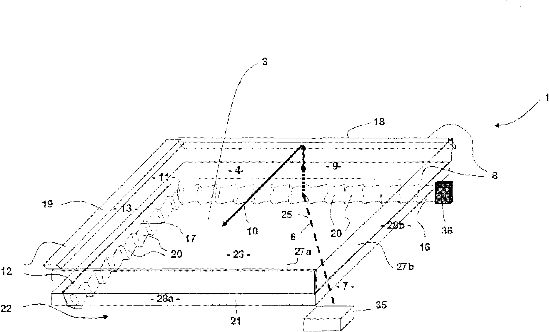
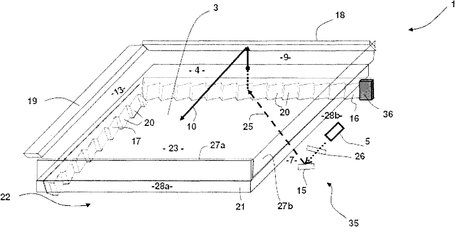
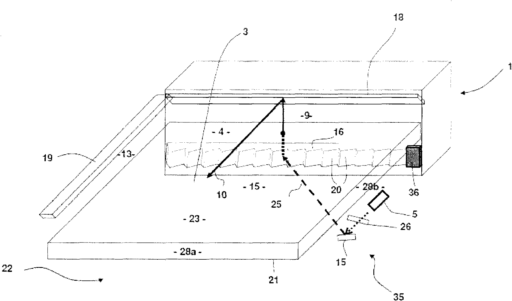
[0035] Referring to the drawings, a sensing system 1 is provided for sensing a touch input 2 on a touch sensitive device 3 . The sensing system 1 comprises a sensing plane 4 and a collimated light source 5 for generating a plurality of light rays 6 along one or more planes 7 different from the sensing plane 4 . Reflecting means 8 are provided near one edge 9 of the sensing plane for converting at least a subset 10 of the light rays 6 into parallel rays and redirecting the subset of rays along the sensing plane 4 . At least one of the light rays 10 along the sensing plane 4 is blocked by the touch input 2, so that the sensing system 1 determines a position coordinate of the touch input.

[0036]Also included is a second said sensing plane 11 which is also different from the one or more planes 7 along which a plurality of light rays 6 are generated. The second said reflecting device 12 is close to an edge 13 of the second sensing plane 11, and is used for converting the second ...


PUM


Abstract

The invention discloses a sensing system for sensing a touch input on a touch sensitive device, wherein the system comprises the following components: a sensing plane; a collimating illuminating source for generating light that transmits along one or more planes different with the sensing plane; and a reflector close to one edge of the sensing plane, which is used for converting at least one light subset into parallel light, and lead the light subset again to let it along the sensing plane; at least one light in the light along the sensing plane is blocked by the touch input, so as to make the sensing system capable of determining one location coordinate of the touch input. The invention also provides a relevant method that senses a touch input on a touch sensitive device.

Description

technical field [0001] The present invention relates to sensing systems for sensing touch input on touch sensitive devices, including but not limited to infrared scanning touch screens. [0002] The present invention is mainly developed for an infrared scanning touch screen display so as to be able to sense a user's touch input on the infrared touch screen display. Although the invention will be described with reference to this particular application, the invention is not limited to this application. Background of the invention [0003] The prior art sensing system usually includes multiple transmitters and multiple receivers, which are respectively used to transmit and receive light passing through the touch screen. When a user obstructs one or more light rays at a touch location on the touch screen, the corresponding receiver stops receiving the light rays so that the orientation of the touch location can be determined. [0004] The sensing system includes infrared (IR) ...

Claims


Application Information

Patent Timeline
Patent Type & Authority Applications(China)
IPC IPC(8): G06F3/042
CPCG06F2203/04109G06F3/0423
Inventor 冯耀军蔡振荣刘颖陈守龙
Owner HONG KONG APPLIED SCI & TECH RES INST
Why Eureka
Try Eureka