Unlock instant, AI-driven research and patent intelligence for your innovation.

Pull chain switch for direct current motor of ceiling fan

A DC motor and zipper technology, applied in electrical switches, electrical components, circuits, etc., can solve the problems of easy wear and tear of metal sheet 97 and contacts 98, and achieve the effect of reducing wear and prolonging service life.

Inactive Publication Date: 2009-12-02
曾腾三
View PDF0 Cites 4 Cited by
  • Summary
  • Abstract
  • Description
  • Claims
  • Application Information

AI Technical Summary

Problems solved by technology

[0007] 1. Please refer to Figure 8A As shown, its starting mode is to pull the slide fastener 95, so that the two contacts 98 on the metal sheet 97 can be instantly contacted on each conductive shrapnel 99; then when the slide fastener 95 is released, as Figure 8B As shown, the actuating disk 93 will be subjected to the elastic force of the torsion spring 94 to cause the actuating disk 93 to rotate in the opposite direction and return to its original state to form an open circuit; The contacts 98 of the metal sheet 97 are in contact with each other, so the contacts 98 on both sides of the metal sheet 97 are easy to wear
[0008] 2. Moreover, when the user pulls the zipper 95 to activate the DC motor, the contact point 98 on the coupling portion 96 of the actuator plate 93 will rotate synchronously and contact the two conductive shrapnels 99 to generate a momentary current to start the DC motor. However, according to the general user habits, since this kind of zipper switch does not have any feeling or sound of starting the switch when starting the DC motor, it is easy to cause the user to have the illusion that the action of starting the DC motor has not been completed

Method used


Image

  • Pull chain switch for direct current motor of ceiling fan
  • Pull chain switch for direct current motor of ceiling fan
  • Pull chain switch for direct current motor of ceiling fan

Examples


Embodiment Construction

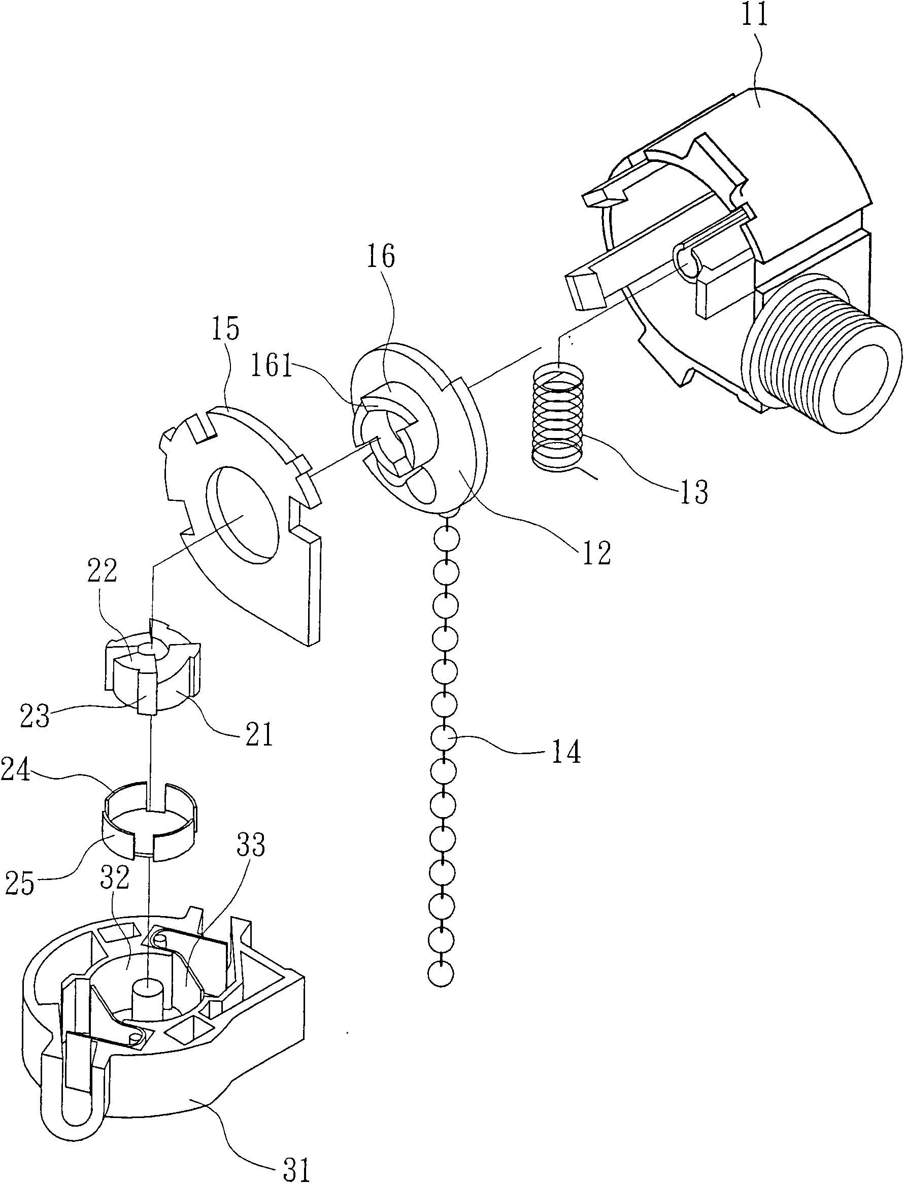
[0036] First, see figure 1 As shown, the present invention provides a zipper switch for a ceiling fan DC motor, which is mainly composed of an upper casing 11, a rotating block 21 and a lower casing 31, wherein:

[0037] The upper casing 11 is pivotally provided with a drive plate 12, an elastic element 13, a zipper 14 and a gland 15. One side of the drive plate 12 is for setting the elastic element 13, and in this embodiment the elastic element 13 is a torsion spring, and the elastic element 13 abuts on one side of the driving plate 12 with its one end, and the other end abuts on the axis at the center of the upper housing 11, and the zipper 14 is connected to the On the drive plate 12, the drive plate 12 can be driven to rotate in one direction, and the drive plate 12 can be pushed against by the elastic force provided by the elastic element 13 to perform a reverse rotation, and the gland 15 is used To cover on one side of the guide plate 12, so as to locate the elastic el...


PUM


Abstract

The invention relates to a pull chain switch for a direct current motor of a ceiling fan, which adopts the scheme that an upper shell is internally pivoted with a priming disk; an elastic element is arranged between the priming disk and the upper shell; the priming disk is connected with a slide fastener; a passive part corresponding to an inclined push face is formed at one end of a rotating block so as to ensure that the inclined push face is unidirectionally clamped on the passive part and can unidirectionally drive the rotating block to carry out segmental circumferential rotations; a lower shell is covered and matched with an upper cover body and provided with an accommodating space for pivoting the rotating block; the rotating block is provided with a metal sheet which forms four conducting contact points mutually distributed with an equal angle along the circumference of the rotating block; and during each circumferential rotation of the rotating block driven by a propping and pushing part, each conducing contact point on the rotating block generates discontinuous electrical contact with a conducting elastic sheet in the lower shell. The pull chain switch achieves the purpose of generating transient current, reduces abrasion, prolongs the service life of each conducting contact point and can avoid generating illusion on operations so as to have more humanization.

Description

technical field [0001] The invention relates to a zip switch for a ceiling fan DC motor. Background technique [0002] In the case of a ceiling fan that generally supplies alternating current, it is implemented by continuously supplying electricity to trigger the ceiling fan or change the speed of the ceiling fan, such as Figure 5 As shown, an existing slide chain switch that can continuously provide power is mainly formed by docking an upper casing 71 and a lower casing 72, and an actuator plate 73, a slide fastener 74, A torsion spring 75 and a gland 76, wherein the driving plate 73 and the torsion spring 75 are pivotally arranged in the center of the upper housing 71, and the zipper 74 is connected to the driving plate 73, and protrudes from the center of the driving plate 73 side. Four pushing parts 76 with slopes; in this way, by pulling the zipper 74, the center of the above housing 71 of the driving plate 73 can be made as the axis, and the pushing parts 76 are drive...

Claims


Application Information

Patent Timeline
IPC IPC(8): H01H17/16H01H17/06
Inventor 曾腾三
Owner 曾腾三