Needle thread feeding device for multi-needle embroidery sewing machine
A technology of feeding device and sewing machine, which is applied to sewing machine measuring device, sewing machine components, embroidery machine mechanism, etc., can solve the problems of detrimental embroidery pattern style, complicated structure of sewing machine head, and time-consuming threading, etc., so as to improve the quality and style. , The effect of eliminating winding defects and reducing the number of rolls
- Summary
- Abstract
- Description
- Claims
- Application Information
AI Technical Summary
Problems solved by technology
Method used
Image
Examples
Embodiment 1
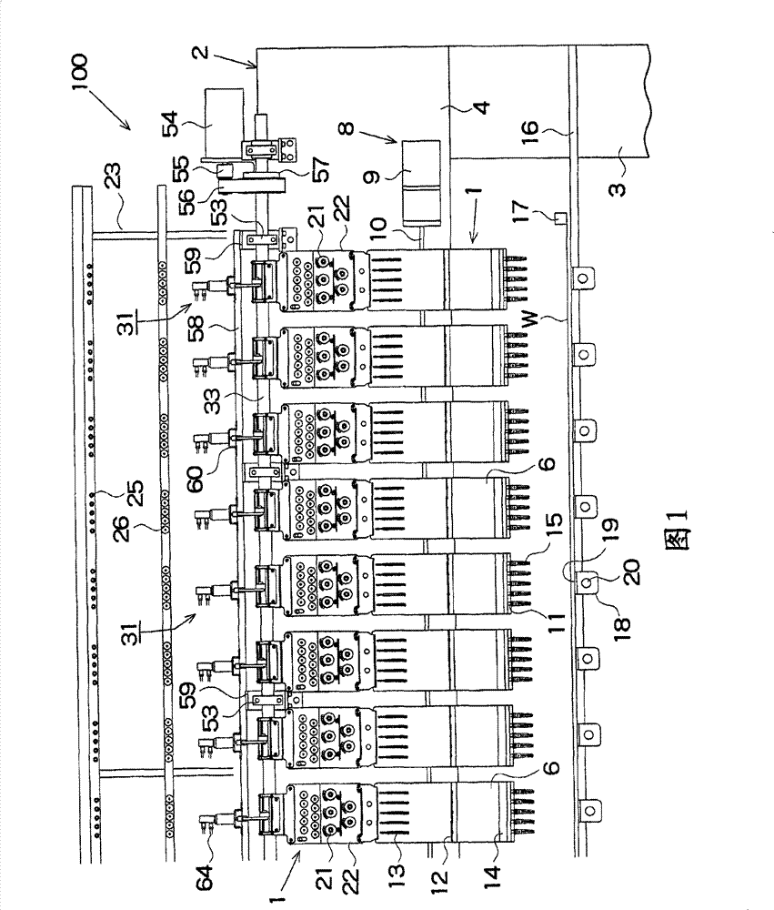
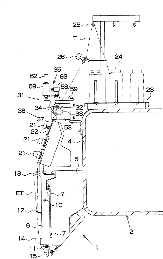
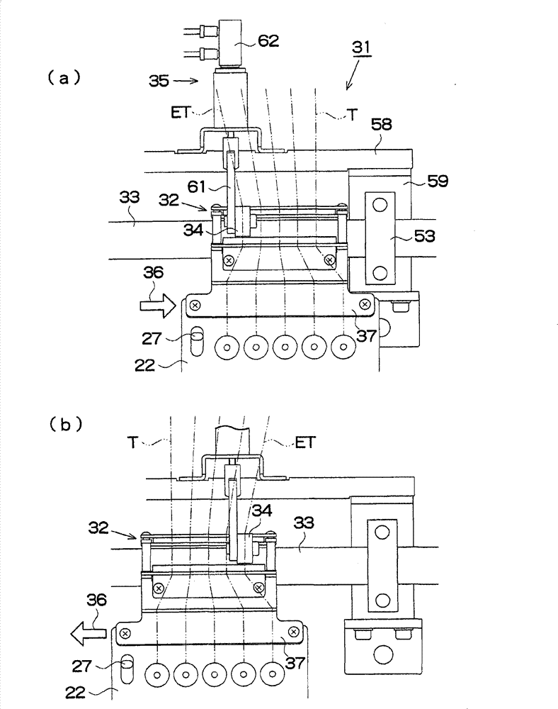
[0022] Below, according to Figure 1 to Figure 8 , to illustrate Embodiment 1 of the present invention. Such as figure 1 , figure 2 As shown, the multi-head embroidery sewing machine 100 of this embodiment is formed by arranging a plurality of (for example, 56) multi-needle embroidery sewing machines 1 in the left-right direction of the machine frame 2 . The sewing machine frame 2 includes a pillar portion 3 and a beam portion 4 , and an arm 5 of the multi-needle embroidery sewing machine 1 is protrudingly provided on the front surface of the beam portion 4 . In front of the sewing machine arm 5, the sewing machine head 6 is slidably supported left and right by the rail 7, and the heads 6 of all the embroidery sewing machines 1 are driven by the motor 9 of the color changing mechanism 8 through the connecting rod 10.
[0023] A plurality of (for example five) needle bars 11, a thread guide 12, a thread take-up 13 and a thread gripper 14 are arranged on the sewing machine h...
Embodiment 2
[0043] Next, according to Figure 9 ~ Figure 11 , to illustrate Embodiment 2 of the present invention. The upper line feeding device 81 of embodiment 2, such as Figure 9 , Figure 10 As shown, the upper thread guide mechanism 82 and the driving roller 83 are arranged on the beam portion 4 of the sewing machine frame 2, and the pressure roller 84 can be moved relative to the beam portion 4, and the wiring mechanism 86 is pressed against the upper thread guide mechanism 82. The roller 84 and the switching mechanism 35 are configured to move in the axial direction of the driving roller 83 . Next, configurations different from those of Embodiment 1 will be described. In the drawings, the same reference numerals as those of the first embodiment denote components already described.
[0044] Such as Figure 10 , Figure 11 As shown, the upper thread guide mechanism 82 includes two thread guides 87, 88 facing up and down at approximately the same interval as the diameter of the...
Embodiment 3
[0048] Next, according to Figure 12 to Figure 14 , to illustrate Embodiment 3 of the present invention. The third embodiment differs from the first embodiment in that the tension stand 22 is not provided and in that another needle thread feeding device 109 different from the needle thread feeding device 31 of the first embodiment is provided. Next, differences between this other needle thread feeding device 109 and the needle thread feeding device 31 of the first embodiment will be described. In the drawings, the same reference numerals as those of the first embodiment denote components already described.
[0049] The upper thread feeding device 109 does not have the base 37 installed on the tension table 22, but is provided with the clamping part 110 shown below, the opening and closing mechanism 140, and the controller (not shown), which is similar to that of the first embodiment in this point The upper wire feeding device 31 is different. In addition, the switching mech...
PUM
 Abstract
Description
Claims
Application Information
 - R&D
- Intellectual Property
- Life Sciences
- Materials
- Tech Scout
- Unparalleled Data Quality
- Higher Quality Content
- 60% Fewer Hallucinations
Browse by: Latest US Patents, China's latest patents, Technical Efficacy Thesaurus, Application Domain, Technology Topic, Popular Technical Reports.
© 2025 PatSnap. All rights reserved.Legal|Privacy policy|Modern Slavery Act Transparency Statement|Sitemap|About US| Contact US: help@patsnap.com


