
Two-stage power supply system

A power supply system, two-stage technology, applied in the direction of power network operating system integration, emergency power supply arrangement, DC power supply parallel operation, etc., can solve the problem of wasting power and achieve the effect of reducing power waste

Inactive Publication Date: 2009-12-09
POWERTECH INDAL
View PDF0 Cites 0 Cited by
  • Summary
  • Abstract
  • Description
  • Claims
  • Application Information

AI Technical Summary

Problems solved by technology

Therefore, general household appliances or commonly used products are usually in a standby state, which wastes a lot of power. Therefore, reducing the standby power of products is the most important issue at present.

Method used


Image

  • Two-stage power supply system
  • Two-stage power supply system
  • Two-stage power supply system

Examples


Embodiment Construction

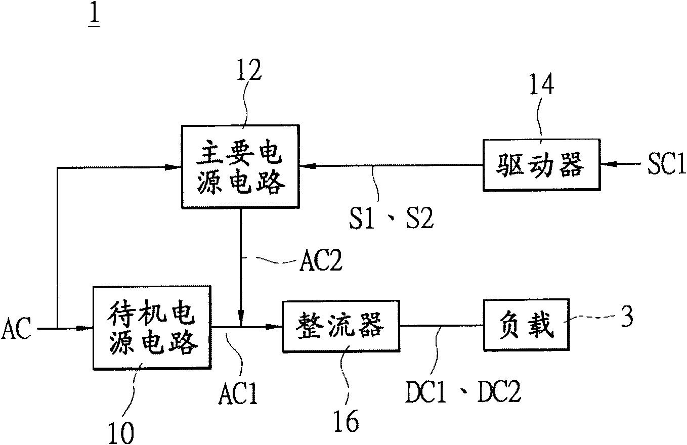
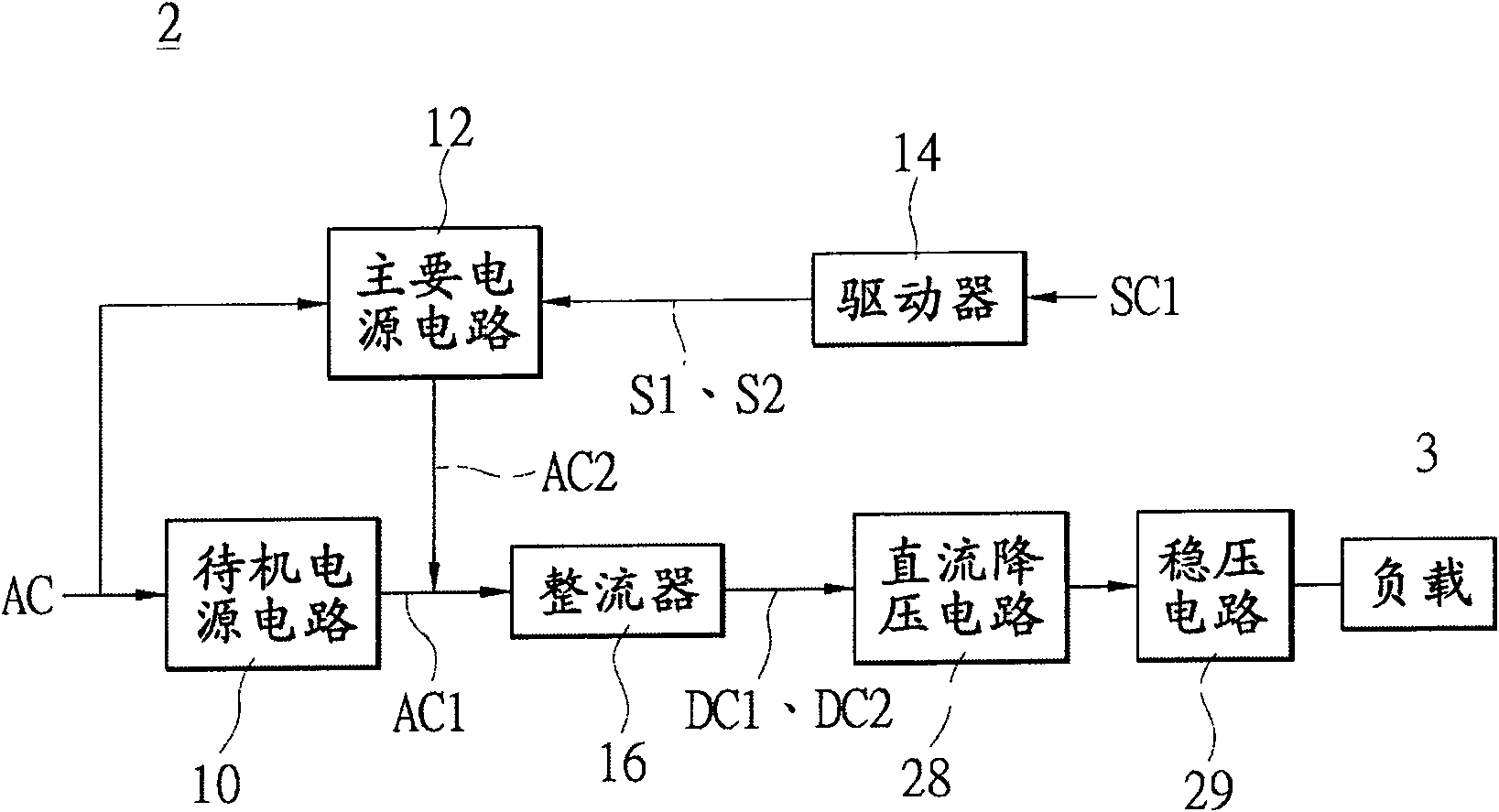
[0038] Please refer to figure 1 , is a circuit block diagram of a two-stage power supply system according to the first preferred embodiment of the present invention. The two-stage power supply system 1 has a standby power supply mode and a normal power supply mode, which can respectively provide power for a load 3 in a standby state or a working state. The two-stage power supply system 1 includes a standby power circuit 10 , a main power circuit 12 , a driver 14 and a rectifier 16 . Wherein, the standby power supply circuit 10 is used for receiving an AC power AC, and stepping down the AC power AC to output a standby AC power AC1. The main power supply circuit 12 is also used to receive the AC power AC and step down the AC power AC to output a main AC power AC2.

[0039] continue to refer figure 1 , the driver 14 is coupled to the main power circuit 12 , and the rectifier 16 is coupled to the standby power circuit 10 , the main power circuit 12 and a load 3 . When the load...


PUM


Abstract

A two-stage power supply system includes a standby power circuit, a main power circuit, a driver and, a rectifier. Moreover, the standby power circuit is used to convert a utility AC (Alternating Current; AC) into a standby AC. The main power circuit is used to convert the utility AC into a main AC. Furthermore, the driver is coupled to the main power circuit so as to control whether or not the main power circuit outputs the main AC to the rectifier. Finally, the rectifier is coupled to the standby power circuit, the main power circuit, and a load, wherein the rectifier rectifies the standby AC alone for outputting a standby DC (Direct Current; DC) to the load, or rectifies an integrated AC of the standby AC and the main AC for outputting a supply DC to the load.

Description

technical field [0001] The invention is a two-stage power supply system, especially a power supply system with a standby power supply mode and a normal power supply mode. Background technique [0002] Due to the rapid reduction of consumable energy such as coal mines and petroleum in the world in recent years, the problem of waste of consumable energy has become increasingly serious, which in turn has made people pay more and more attention to the issues of environmental protection, energy conservation and green energy. At present, countries such as the European Union, California in the United States, South Korea, and Japan have set their standards for the standby state of some products (standby power<1W). At the same time, many home appliances have already adopted energy-saving designs. import it. [0003] After many experts discussed, tested and evaluated, they agreed that in order to achieve energy saving of products, it is necessary to start with the power consumptio...

Claims


Application Information

Patent Timeline
Patent Type & Authority Applications(China)
IPC IPC(8): H02J1/10H02M7/04H02M5/06H02M3/06
CPCH02J9/005H02M7/05Y02B70/30Y04S20/20
Inventor 李裕隆程聪华郑国田
Owner POWERTECH INDAL
Learn More