A temperature-compensated circuit and method thereof

A circuit, ambient temperature technology, applied in electrical components, generating electrical pulses, output stability, etc., can solve problems such as increasing circuit costs

Inactive Publication Date: 2009-12-09
AVAGO TECH ECBU IP (SINGAPORE) PTE LTD
View PDF4 Cites 24 Cited by
  • Summary
  • Abstract
  • Description
  • Claims
  • Application Information

AI Technical Summary

Problems solved by technology

This special requirement increases circuit cost

Method used


Image

  • A temperature-compensated circuit and method thereof
  • A temperature-compensated circuit and method thereof
  • A temperature-compensated circuit and method thereof

Examples


Embodiment Construction

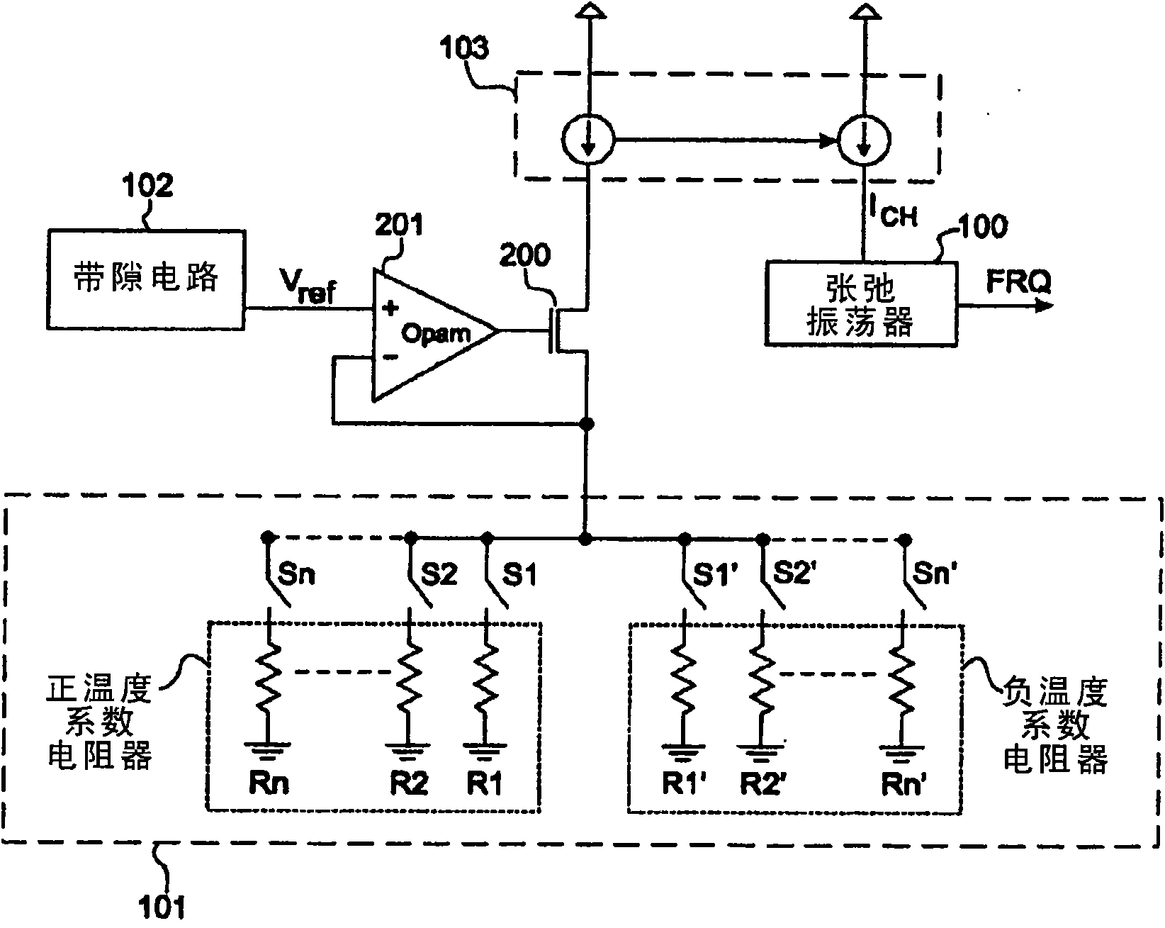
[0024] In various embodiments of the invention, temperature compensated relaxation oscillator circuits, such as temperature compensated CMOS monolithic relaxation oscillator circuits, and corresponding assemblies and methods are provided wherein the output signal provided by the relaxation oscillator circuit is The frequency is essentially insensitive to temperature changes.

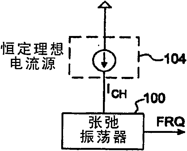
[0025] The problems and disadvantages of the prior art relaxation oscillator circuits described above are overcome in various embodiments of the present invention.

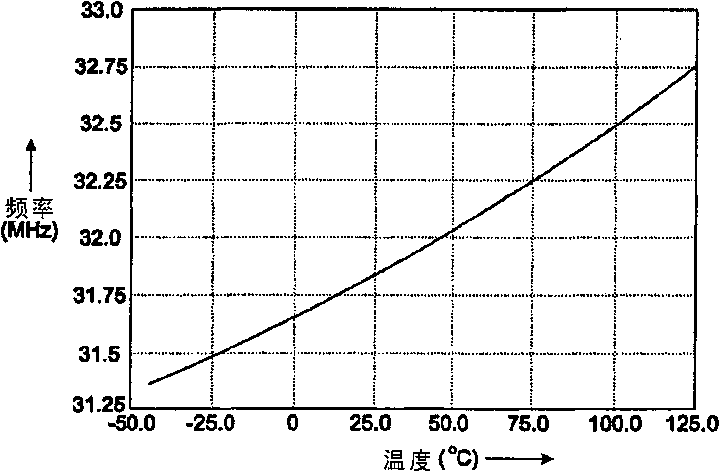
[0026] For example, one embodiment of the relaxation oscillator circuit of the present invention achieves a very low temperature coefficient of about 5 ppm / °C under typical process corner simulation conditions. On the contrary, as in U.S. Patent No.6,157,270 of Tso and in Maxim Relaxation OscillatorProduct MAX7384 (see http: / / datasheets.maxim-ic.com / en / ds / MAX7384.pdf ), providing respective temperature coefficients of 294 ppm / °C and ±550 p...


PUM


Abstract

The present invention discloses a temperature-compensated circuit and method thereof. Disclosed are various embodiments of temperature-compensated relaxation oscillator circuits that may be fabricated using conventional CMOS manufacturing techniques. The relaxation oscillator circuits described herein exhibit superior low temperature coefficient performance characteristics, and do not require the use of expensive off-chip high precision resistors to effect temperature compensation. Positive and negative temperature coefficient resistors arranged in a resistor array offset one another to provide temperature compensation in the relaxation oscillator circuit.

Description

technical field [0001] Various embodiments of the invention described herein relate to the field of monolithic integrated circuits, and more particularly to CMOS monolithic relaxation oscillator circuits, and components, devices associated therewith, that are substantially insensitive to temperature variations , systems and methods. Background technique [0002] Oscillators are widely used in various microelectronic systems for purposes such as providing clock signals. In some applications, oscillators are used to generate a steady-state clock signal that is relatively insensitive to temperature changes. For example, some oscillators in motion control encoders are required to operate in a wide temperature range, such as between -40 to 125 degrees Celsius. [0003] To obtain an accurate and stable clock signal over such a wide temperature range, designers typically use external components such as crystals and inductors. However, these external solutions impose a high cost ...

Claims


Application Information

Patent Timeline
Patent Type & Authority Applications(China)
IPC IPC(8): H03L7/00H03K3/011H03L1/02
CPCH03K3/011H03K3/0231
Inventor 艾利克斯·建中·陈陈吉恩谭同棣潘国振
Owner AVAGO TECH ECBU IP (SINGAPORE) PTE LTD
Why Eureka
Try Eureka