Sound judging device, sound sensing device, and sound judging method

A judging device and sound detection technology, applied in speech analysis, speech recognition, instruments, etc., can solve problems such as inability to judge extracted sounds, distortion of spectrum shape, etc.

Active Publication Date: 2009-12-09
PANASONIC HLDG CORP KADOMA SHI
View PDF2 Cites 89 Cited by
  • Summary
  • Abstract
  • Description
  • Claims
  • Application Information

AI Technical Summary

Problems solved by technology

For this reason, if large noise is mixed in, the shape of the frequency spe

Method used


Image

  • Sound judging device, sound sensing device, and sound judging method
  • Sound judging device, sound sensing device, and sound judging method
  • Sound judging device, sound sensing device, and sound judging method

Examples


Embodiment 1

[0130] Figure 5 It is an external view of the noise removing device in Embodiment 1 of the present invention. The noise removal device 100 includes a frequency analysis unit, an extracted sound determination unit, and a sound extraction unit, and is realized by executing a program for realizing the functions of these processing units on a CPU that constitutes one component of a computer. Also, various intermediate data, execution result data, and the like are stored in the memory.

[0131] Figure 6 as well as Figure 7 is a block diagram of the structure of the noise removing device in Embodiment 1 of the present invention.

[0132] exist Figure 6 Among them, the noise removal device 100 includes: an FFT (Fast Fourier Transform) analysis unit 2402 (frequency analysis unit) and a noise removal processing unit 101 (consisting of an extracted sound determination unit and a sound extraction unit). The FFT analysis unit 2402 and the noise removal processing unit 101 are rea...

Embodiment 2

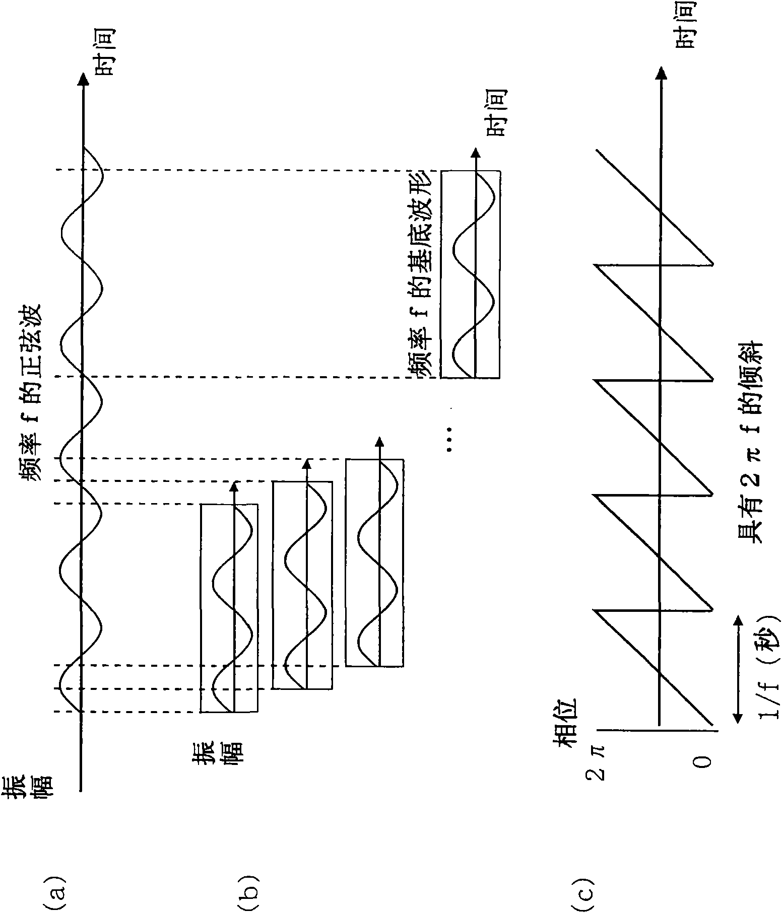
[0253] Hereinafter, the noise removal device according to the second embodiment will be described. The noise removal device according to the second embodiment is different from the noise removal device according to the first embodiment. When the phase of the frequency signal at time t of the mixed sound is ψ(t) (radian), the phase is corrected to ψ′ (t)=mod 2π(ψ(t)-2πft) (f is the analysis frequency), use the phase ψ′(t) of the corrected frequency signal to judge the frequency signal of the extracted sound and remove the noise.

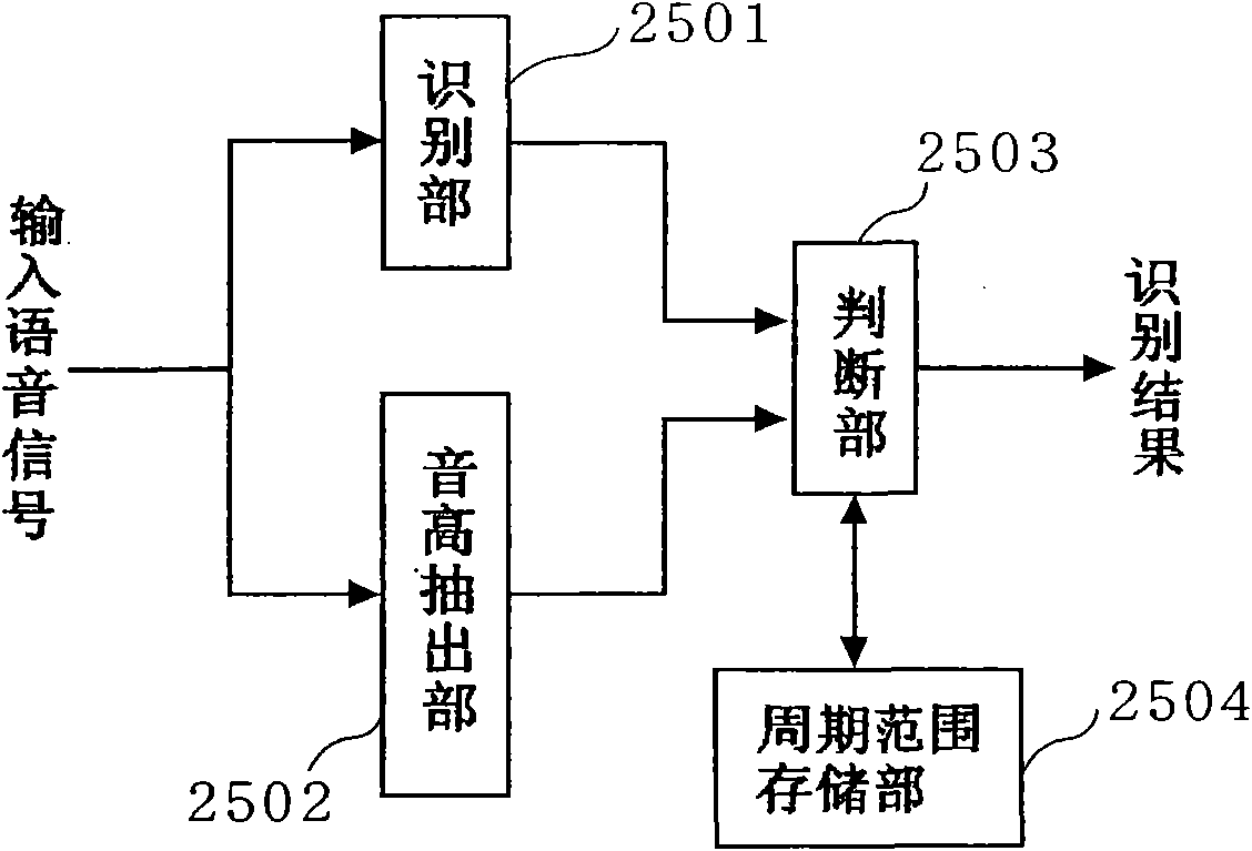
[0254] Figure 26 as well as Figure 27 It is a block diagram showing the structure of the noise removing device in Embodiment 2 of the present invention.

[0255] exist Figure 26 Among them, the noise removal device 1500 includes: an FFT analysis unit 2402 (frequency analysis unit) and a noise removal processing unit 1504 . The noise removal processing unit 1504 includes a phase correction unit 1501(j) (j=1 to M), an extracted sound determinatio...

Embodiment 3

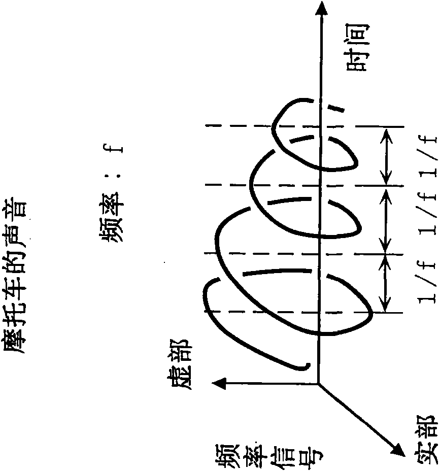
[0338] Hereinafter, the vehicle detection device according to the third embodiment will be described. The vehicle detection device according to Embodiment 3 outputs an extracted sound detection flag when it is judged that there is a frequency signal of an engine sound (extracted sound) from at least one of the mixed sounds input from a plurality of microphones, and sends the signal to The driver is notified of an approaching vehicle. At this time, from the approximate straight line in the space represented by the time and phase, the mixed sound suitable for each time-frequency region is obtained in advance, and the phase is obtained from the distance between the obtained straight line and the phase for the obtained analysis frequency. distance, and judge the frequency signal of the engine sound.

[0339] Figure 36 and Figure 37 It is a block diagram showing the configuration of the vehicle detection device in Embodiment 3 of the present invention.

[0340] exist Figure...


PUM


Abstract

A sound determination device (100) includes: an FFT unit (2402) which receives a mixed sound including a to-be-extracted sound and a noise, and obtains a frequency signal of the mixed sound for each of a plurality of times included in a predetermined duration; and a to-be-extracted sound determination unit (101 (j)) which determines, when the number of the frequency signals at the plurality of times included in the predetermined duration is equal to or larger than a first threshold value and a phase distance between the frequency signals out of the frequency signals at the plurality of times is equal to or smaller than a second threshold value, each of the frequency signals with the phase distance as a frequency signal of the to-be-extracted sound. The phase distance is a distance between phases of the frequency signals when a phase of a frequency signal at a time t is psi (t) (radian) and the phase is represented by psi' (t) = mod 2 pi (psi (t) - 2 pi f t) (where f is an analysis-target frequency).

Description

technical field [0001] The present invention relates to a sound judging device for judging the frequency signal of an extracted sound contained in a mixed sound according to a time-frequency region, and particularly relates to sounds having timbres such as engine sounds, alarm sounds, voices, etc., and wind noises, rain sounds, background noises, etc. The sounds with timbre are distinguished, and the frequency signal of the sound with timbre (or the sound without timbre) is judged according to the time-frequency region. Background technique [0002] The first prior art is to extract a pitch cycle from an input speech signal (mixed sound), and if the pitch cycle is not extracted, it is judged to be noise (for example, refer to Patent Document 1). In the first prior art, speech is recognized from input speech judged as speech candidates. [0003] figure 1 It is a block diagram showing the structure of a noise removing device according to the first prior art described in Pate...

Claims


Application Information

Patent Timeline
IPC IPC(8): G10L21/02G10L15/20G10L21/0232G10L25/18G10L25/78G10L25/84
CPCG10L2025/783G10L21/0208G10L2025/937
Inventor 芳泽伸一中藤良久
Owner PANASONIC HLDG CORP KADOMA SHI
Why Eureka
Try Eureka