
Sound determination device, sound detection device, and sound determination method

a technology of detection device and sound, applied in the direction of transducer casing/cabinet/support, electrical transducer, instruments, etc., can solve the problems of the inability to apply the configuration to the technique of extracting only the to-be-extracted sound from the mixed sound, and the inability to determine the to-be-extracted sound. to achieve the effect of accurate recognition of the sound

Inactive Publication Date: 2010-08-26
PANASONIC CORP
View PDF10 Cites 33 Cited by
  • Summary
  • Abstract
  • Description
  • Claims
  • Application Information

AI Technical Summary

Benefits of technology

[0016]Further, the time width used to calculate a phase distance is determined to be within a range from 2 to 4 times a time window width (corresponding to a time resolution) of a window function. With this, it is possible to determine a time width used to calculate a phase distance based on the time resolution (the time window width of the window function), thereby making it possible to determine frequency signals of a to-be-extracted sound using various time resolutions. The use of suitable time resolutions makes it possible to accurately determine a to-be-extracted sound particularly in the case of determining frequency signals of a to-be-extracted sound having a temporally varying frequency structure. For example, fine time resolutions are used to determine frequency signals of a to-be-extracted sound such as a voice having a frequency structure which varies significantly and quickly, and rough time resolutions (fine frequency resolutions) are used to determine frequency signals of a to-be-extracted sound such as an engine sound during an idle running state having a frequency structure which varies slowly.
[0030]With this structure, it is possible to use the frequency signals, of the to-be-extracted sound, determined on a per time-frequency domain basis. For this, for example, an audio output device with an embedded noise removal device according to the present invention can reproduce a clear extracted sound from which noises have been removed. In addition, a sound source direction detection device with an embedded noise removal device according to the present invention can calculate a sound source direction of a clear extracted sound from which noises have been removed. In addition, a sound recognition device with an embedded noise removal device according to the present invention can accurately recognize a sound even when the sound is surrounded by noises.

Problems solved by technology

In addition, it is impossible to determine a sound having a varying pitch cycle such as an engine sound (having a pitch cycle varying depending on the number of turns of the engine).
For this, it is impossible to determine a to-be-extracted sound when the sound includes great noises causing distortion in the spectrum shape.
In addition, since the third conventional technique is configured to code an audio signal, it is difficult to apply the configuration to a technique of extracting only a to-be-extracted sound from a mixed sound.

Method used


Image

  • Sound determination device, sound detection device, and sound determination method
  • Sound determination device, sound detection device, and sound determination method
  • Sound determination device, sound detection device, and sound determination method

Examples


embodiment 1

Variation 2 of Embodiment 1

[0179]Next, a description is given of Variation 2 of the noise removal device shown in Embodiment 1.

[0180]The noise removal device according to Variation 2 is structurally similar to the noise removal device according to Embodiment 1 described with reference to FIGS. 6 and 7, but is different in processing performed by the noise removal processing unit 101.

[0181]The phase distance determination unit 201(j) in the to-be-extracted sound determination unit 101(j) generates a phase histogram using frequency signals at time points of a 1 / f time interval selected by the frequency signal selection unit 200(j). The phase distance determination unit 201(j) determines, to be frequency signals 2408 of a to-be-extracted sound, the frequency signals having a phase distance equal to or smaller than a second threshold value and having the number of times of appearance equal to or greater than a first threshold value.

[0182]Lastly, the sound extraction unit 202(j) removes ...

embodiment 2

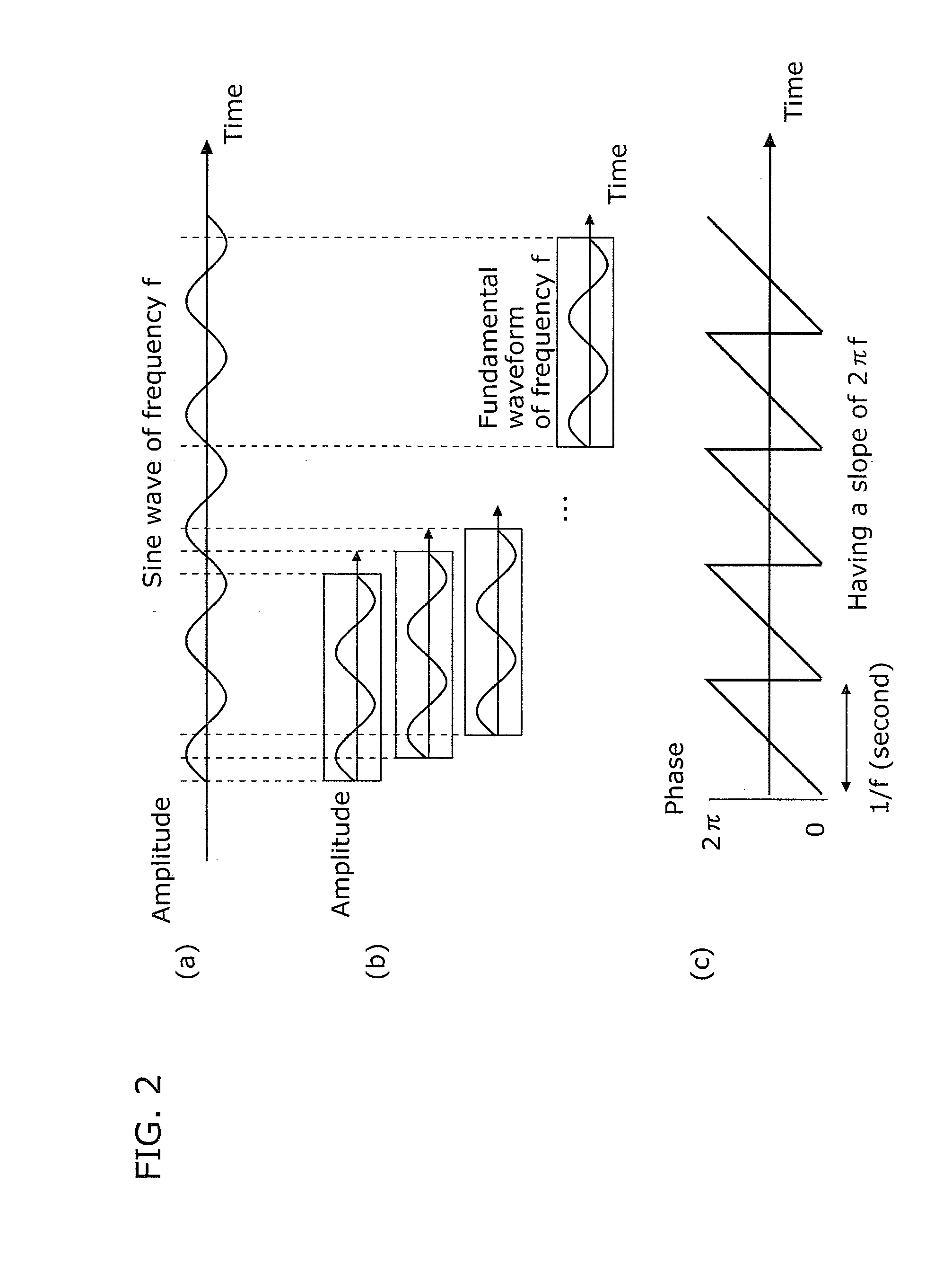
[0201]Next, a noise removal device according to Embodiment 2 is described. Unlike the noise removal device according to Embodiment 1, the noise removal device according to Embodiment 2 modifies the phase ψ(t) (radian) of a frequency signal at a current time point t of a mixed sound to ψ′(t) according to the expression ψ′(t)=mod 2π(ψ(t)−2πft) (here, f denotes a reference frequency), determines a frequency signal of the to-be-extracted sound, based on the modified phase ψ′(t) of the frequency signal, and removes noises.

[0202]Each of FIG. 26 and FIG. 27 is a block diagram showing the structure of the noise removal device according to Embodiment 2 of the present invention.

[0203]In FIG. 26, the noise removal device 1500 includes: an FFT analysis unit 2402 (frequency analysis unit); and a noise removal processing unit 1504 including a phase modification unit 1501(j) (j=1 to M), a to-be-extracted sound determination unit 1502(j) (j=1 to M), and a sound extraction unit 1503(j) (j=1 to M).

[0...

embodiment 3

[0251]Next, a description is given of a vehicle detection device according to Embodiment 3. The vehicle detection device according to Embodiment 3 is intended to notify a driver of the presence of an approaching vehicle by outputting a to-be-extracted sound detection flag when it is determined that a frequency signal of an engine sound (to-be-extracted sound) is included in at least one of mixed sounds inputted through microphones. At this time, first, a reference frequency suitable for the mixed sound is determined for each time-frequency domain in advance based on an approximate straight line represented in time and phase space. Subsequently, with regard to the determined reference frequency, the phase distance is determined based on the distance between the determined straight line and the phase, thereby determining a frequency signal of an engine sound.

[0252]Each of FIG. 36 and FIG. 37 is a block diagram showing a structure of the vehicle detection device according to Embodiment...


PUM


Abstract

A noise removal device includes: an FFT analysis unit which receives a mixed sound including to-be-extracted sounds and noises, and determines frequency signals at time points in a time width; and a to-be-extracted sound determination unit which determines, for each to-be-extracted sound, frequency signals at the time points, satisfying conditions of (i) being equal to or greater than a first threshold value in number and (ii) having a phase distance between the frequency signals that is equal to or smaller than a second threshold value, wherein the phase distance is a distance between phases ψ′(t) of the condition-satisfying frequency signals when a phase of a frequency signal at a current time point t is ψ(t) (radian) and the phase ψ′(t) is mod 2π(ψ(t)−2πft), f denoting a reference frequency, and the predetermined time width is within 2 to 4 times the time window widths of the window functions.

Description

CROSS REFERENCE TO RELATED APPLICATION[0001]This is a continuation application of PCT application No. PCT / JP2009 / 004855, filed on Sep. 25, 2009, designating the United States of America.BACKGROUND OF THE INVENTION[0002](1) Field of the Invention[0003]The present invention relates to a sound determination device which determines frequency signals of to-be-extracted sounds included in a mixed sound on a per time-frequency domain basis, and in particular to a sound determination device which separates toned sounds such as an engine sound, a siren sound, and a voice, in distinction from toneless sounds such as a wind noise, a rain sound, and a background noise, and determines frequency signals of a toned sound (or a toneless sound) on a per time-frequency domain basis.[0004](2) Description of the Related Art[0005]There are first conventional techniques intended to try to extract pitch cycles of an input audio signal (a mixed sound), and determine a sound having no pitch cycle to be a no...

Claims


Application Information

Patent Timeline
IPC IPC(8): H04B15/00G10L21/0208G10L21/0232G10L25/18G10L25/51G10L25/78G10L25/84
CPCG10L21/0216G10L21/0208
Inventor YOSHIZAWA, SHINICHINAKATOH, YOSHIHISA
Owner PANASONIC CORP
Learn More