Floating ballast mass active stethoscope or sound pickup device

a stethoscope and ballast mass technology, applied in the field of sound detection and augmenting, can solve the problems of poor signal-to-noise performance of most electronic stethoscopes, difficult to learn, and a specialty art in stethoscope design, and achieve the effect of reducing nois

Active Publication Date: 2013-03-12
STETHOSCOPE TECH
View PDF22 Cites 35 Cited by
  • Summary
  • Abstract
  • Description
  • Claims
  • Application Information

AI Technical Summary

Benefits of technology

[0038]The design of preferred embodiments of the inventive active stethoscope departs from conventional resonant air column designs while providing a resonant chamber in the stethoscope's chest piece behind the diaphragm as do conventional resonant air column designs. These preferred embodiments represent an advance over the design described in cited U.S. Pat. No. 6,587,564 to Cusson in that they incorporate a floating mass mounted to the stethoscope diaphragm (at one or more coupling points of the diaphragm) and an acoustic transducer referenced to the floating mass. The floating mass has freedom to move in sympathy with the diaphragm's coupling point (or points), relative to the body of the stethoscope's chest piece, so as to stabilize the diaphragm. The stethoscope's acoustic transducer (e.g., microphone) rides with the floating mass to which it is mounted as the floating mass moves during detection of body sound. The floating mass thus stabilizes the acoustic transducer as well as the diaphragm. In typical use, the patient's skin also provides damping to reduce noise that would otherwise reach the acous

Problems solved by technology

Stethoscope design is a specialty art, difficult to learn due to the low sound levels emitted by the body.
Most electronic stethoscopes exhibit poor signal-to-noise performance.
Also, general ambient noise is present at this low level.
This presents a difficult, two-fold problem that affects all stethoscopes: (a

Method used


Image

  • Floating ballast mass active stethoscope or sound pickup device
  • Floating ballast mass active stethoscope or sound pickup device
  • Floating ballast mass active stethoscope or sound pickup device

Examples


sixteenth embodiment

A High Ambient Noise Rejecting Stethoscope or Sound Detection Device

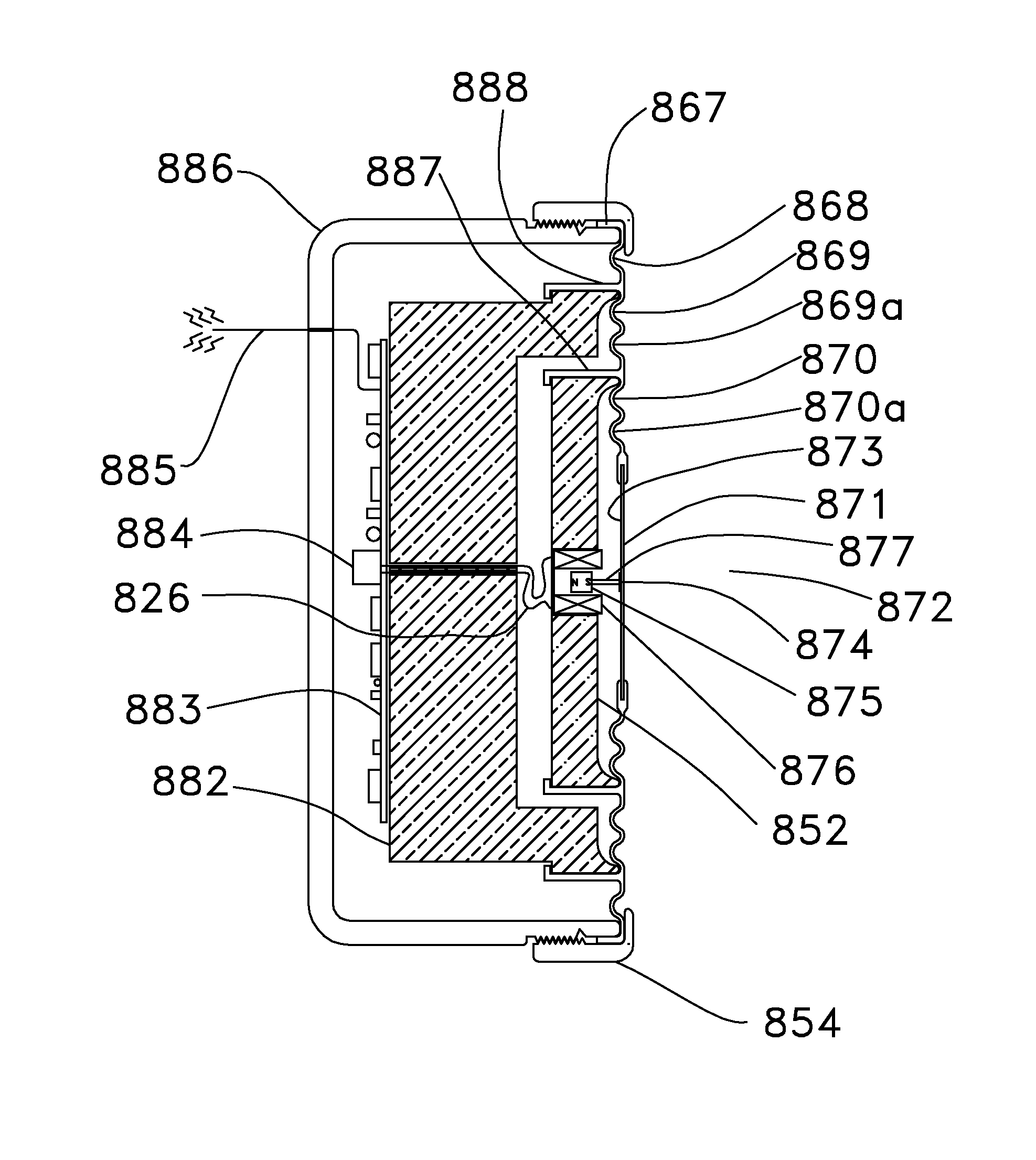
[0192]FIG. 25 is a stylized half section of an embodiment of an electronic, high ambient noise rejecting, sound detection device (772) which can function as a stethoscope chest piece and is built according to the present invention. Device 772 comprises an optical fiber 774 having a section that is wound into a transducer coil portion 726 (the coil section between floating mass 752 and diaphragm membrane 771 which has circular appearance as viewed in FIG. 25). Fiber 774's transducer coil portion 726 (and / or at least one portion of fiber 774 adjacent thereto) is mounted to floating mass 752, and the transducer coil portion 726 biased against (or mounted to) inner face 773 of diaphragm membrane 771 so as to remain in contact with face 773 as shown in FIG. 25 during operation. Typically, the transducer coil portion 726 of optical fiber 774 is bonded to both mass 752 and face 773.

[0193]In operation of the FIG. 25 device,...


PUM


Abstract

An active stethoscope or other sound detection device, including a diaphragm, at least one floating mass mounted to the diaphragm (at at least one coupling point of the diaphragm), and an acoustic transducer mounted to the floating mass. Preferably, each floating mass is configured and mounted so that as each floating mass and each coupling point of the diaphragm move in sympathy with acoustic waves (to be detected) that impinge on the diaphragm, the acoustic transducer rides with and is stabilized by the floating mass to which it is mounted and the diaphragm is stabilized by each floating mass. The acoustic transducer can be of any of many different types. For example, it can be a microphone, or an optical, capacitive, or inductive transducer. The diaphragm can have an isolating portion which absorbs acoustic surface wave energy incident thereon, or otherwise prevents or reduces transmission of acoustic surface waves through the isolating portion between regions of the diaphragm.

Description

BACKGROUND[0001]1. Field of the Invention[0002]The present invention relates to detection of sounds and augmentation of detected sounds above ambient noise. In a class of embodiments, it relates to detection of sounds propagating from within human or animal bodies (e.g., sounds from the heart or lungs) using an active stethoscope configured to augment the sounds of interest above ambient noise.[0003]2. Prior Art[0004]Throughout this disclosure, including in the claims, the expression “active” stethoscope (or “active” sound detection device) denotes a stethoscope (or sound detection device) that includes an acoustic transducer useful for converting acoustic waves (e.g., body sounds of interest) into another form of energy.[0005]Herein, the expression “electronic” stethoscope (or “electronic” sound detection device) denotes a stethoscope (or sound detection device) that includes an acoustic transducer useful for converting acoustic waves of interest (e.g., body sounds) into at least o...

Claims


Application Information

Patent Timeline
IPC IPC(8): A61B7/04A61B7/02
CPCA61B7/04
Inventor BILAN, FRANK ALBERT
Owner STETHOSCOPE TECH
Why Eureka
Try Eureka