High-pressure sprayer

A high-pressure sprayer and nozzle technology, applied in the field of agricultural equipment, can solve the problems of inconvenience for users, unbalanced sprayer, high labor intensity, etc., and achieve the effects of convenient operation, ensuring the amount of liquid medicine, and simple structure

Inactive Publication Date: 2011-04-13
JINGJIANG WEIYI INTPROP SERVICE
View PDF0 Cites 1 Cited by
  • Summary
  • Abstract
  • Description
  • Claims
  • Application Information

AI Technical Summary

Problems solved by technology

[0002] Sprayer is a commonly used agricultural equipment. Its spraying is usually done manually or electrically. It not only increases the self-weight of the sprayer, but also improves the maintenance rate of the sprayer. For this reason, people have developed and designed a pre-inflated high-pressure sprayer, which achieves the purpose of automatic spraying by pre-inflating the inner tank of the sprayer. When the internal medicinal liquid is used up, the internal gas can be self-locked for storage so that it can be used next time. However, the two inner tanks of this sprayer are respectively fed with liquid through their own self-locking devices. There are pressure gauges and pressure reducing valves, so they are connected by pipelines, and the prefilled gas in the two inner tanks can flow with each other. In actual use, due to the difference in the locking and sealing of the self-locking device, it is easy to produce two The unbalanced state when the liquid enters one inner tank, and when spraying the liquid medicine, the liquid medicine in the two inner tanks is ejected first and then later, forming a situation where the remaining liquid medicine in one inner tank and the other inner tank is unequal , making the sprayer unbalanced, causing inconvenience to the user

Method used


Image

  • High-pressure sprayer
  • High-pressure sprayer
  • High-pressure sprayer

Examples


Embodiment Construction

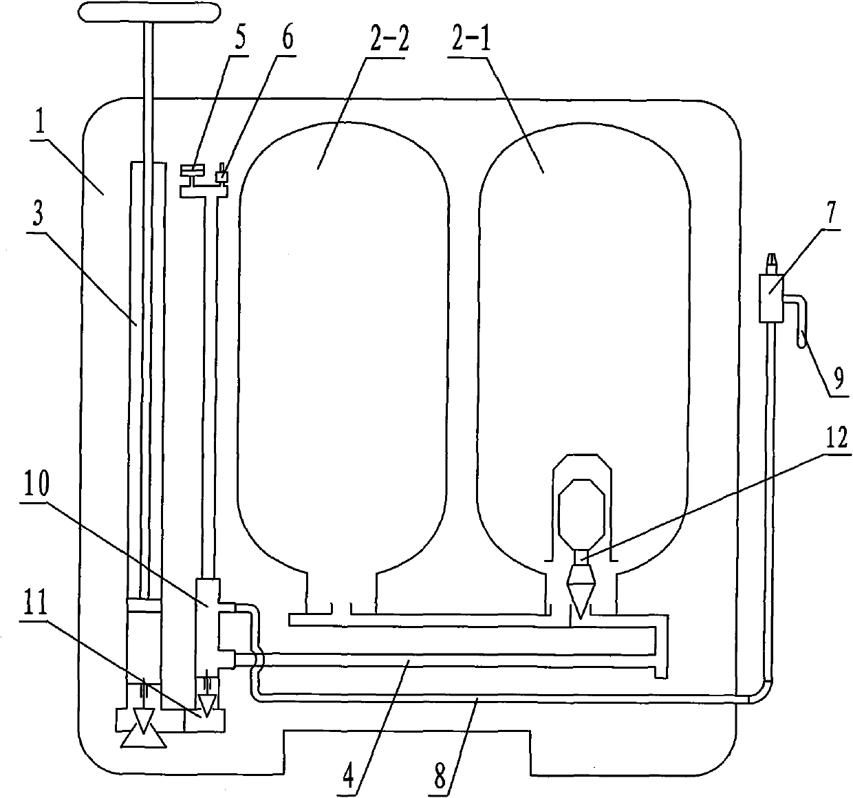
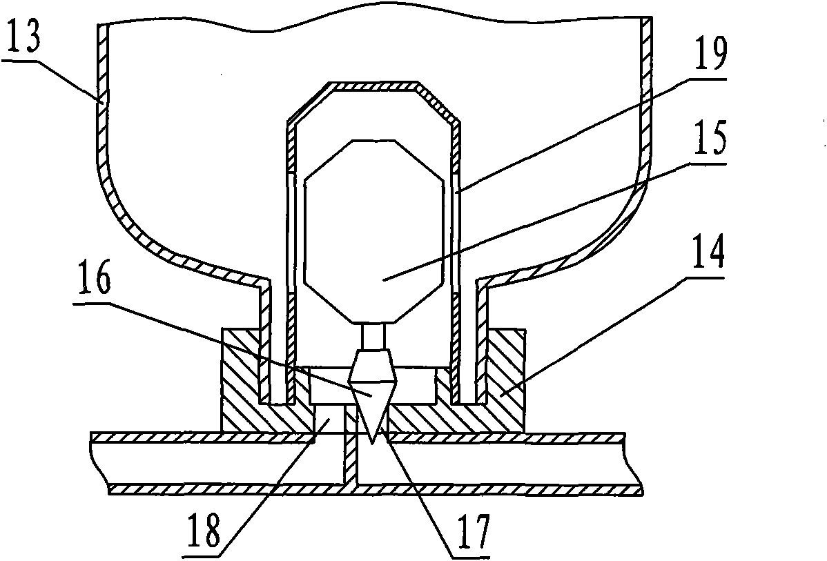
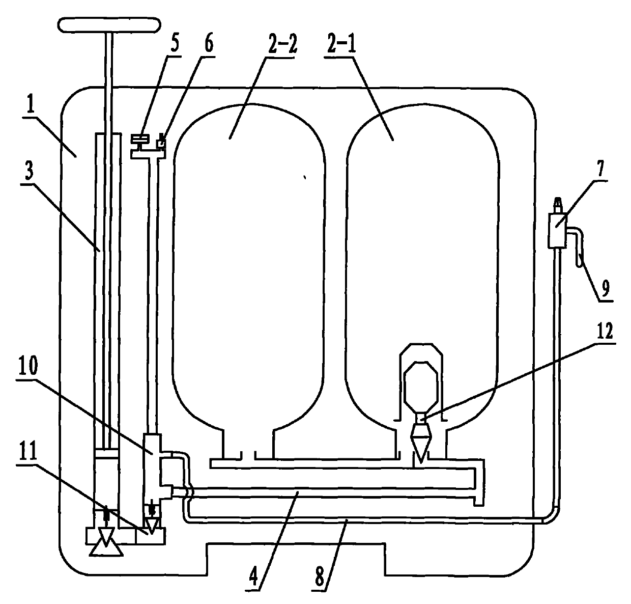
[0015] The present invention will be further described now in conjunction with accompanying drawing. These drawings are all simplified schematic diagrams, which only illustrate the basic structure of the present invention in a schematic manner, so they only show the configurations related to the present invention.

[0016] Such as figure 1 A high-pressure sprayer shown includes an outer barrel body 1, and the outer barrel body 1 is provided with two inner tanks 2-1, 2-2, a filling pump 3, a liquid inlet pipe 4, a pressure gauge 5 and a pressure reducing valve 6. The spray head 7 is located outside the outer barrel body 1. The spray head 7 communicates with the inner tank 2-1 and 2-2 through the liquid outlet pipe 8. The nozzle 7 is provided with a stop valve 9 to control the opening and closing of the spray. The inner tank 2- 1, 2-2 materials can be made of lightweight, pressure-resistant, high-strength polyester material, the liquid inlet pipe 4 communicates with the bottoms...


PUM


Abstract

The invention discloses a high-pressure sprayer, which comprises an outer barrel body, two inner liners, a charging pump, a liquid outlet pipe, a liquid inlet pipe, a spray head, a pressure gauge and a pressure reducing valve, wherein the two inner liners and the charging pump are arranged in the outer barrel body; the liquid inlet pipe is communicated with the bottoms of the two inner liners; a four-way joint is also arranged in the outer barrel body; the four-way joint is communicated with the charging pump, the liquid inlet pipe, the liquid outlet pipe, the pressure gauge and the pressure reducing valve by pipes respectively; the communicated part of the four-way joint and the bottom of the charging pump is provided with a one-way valve; and the communicated part of the liquid inlet pipe and one of the inner liners is provided with a sealed self-locking device which can synchronously control liquid inlet or liquid outlet of the two inner liners. The high-pressure sprayer has simplestructure and convenient operation, ensures the balance of liquor amount during charging the two inner liners, prevents the phenomenon of producing un-equality, and also ensures the balance of gas pressure in the two inner liners; therefore, during spraying, the liquors in the two inner liners can be basically sprayed up at the same time but do not produce imbalance, and can effectively seal and self-lock the reserved gas inside the inner liners when the liquor in the inner liners is used up.

Description

technical field [0001] The invention relates to an agricultural implement, in particular to a high-pressure sprayer. Background technique [0002] Sprayer is a commonly used agricultural equipment. Its spraying is usually done manually or electrically. It not only increases the self-weight of the sprayer, but also improves the maintenance rate of the sprayer. For this reason, people have developed and designed a pre-inflated high-pressure sprayer, which achieves the purpose of automatic spraying by pre-inflating the inner tank of the sprayer. When the internal medicinal liquid is used up, the internal gas can be self-locked for storage so that it can be used next time. However, the two inner tanks of this sprayer are respectively fed with liquid through their own self-locking devices. There are pressure gauges and pressure reducing valves, so they are connected by pipelines, and the prefilled gas in the two inner tanks can flow with each other. In actual use, due to the dif...

Claims


Application Information

Patent Timeline
Patent Type & Authority Patents(China)
IPC IPC(8): B05B9/04B05B12/00B05B15/00
Inventor 华尚兴
Owner JINGJIANG WEIYI INTPROP SERVICE
Why Eureka
Try Eureka