Multiple well pumping unit

A pumping unit and oil pumping technology, which is applied to drilling equipment, wellbore/well components, production fluids, etc., and can solve problems such as poor implementation

Active Publication Date: 2013-05-22
SHANGHAI JIAOTONG UNIV
View PDF1 Cites 2 Cited by
  • Summary
  • Abstract
  • Description
  • Claims
  • Application Information

AI Technical Summary

Problems solved by technology

However, it can only be applied to two wells, the design of the pumping unit is closely related to the design of the oil well, and the implementation is poor

Method used


Image

  • Multiple well pumping unit
  • Multiple well pumping unit

Examples


Embodiment Construction

[0013] The embodiments of the present invention are described in detail below. This embodiment is implemented on the premise of the technical solution of the present invention, and detailed implementation methods and specific operating procedures are provided, but the protection scope of the present invention is not limited to the following implementation example.

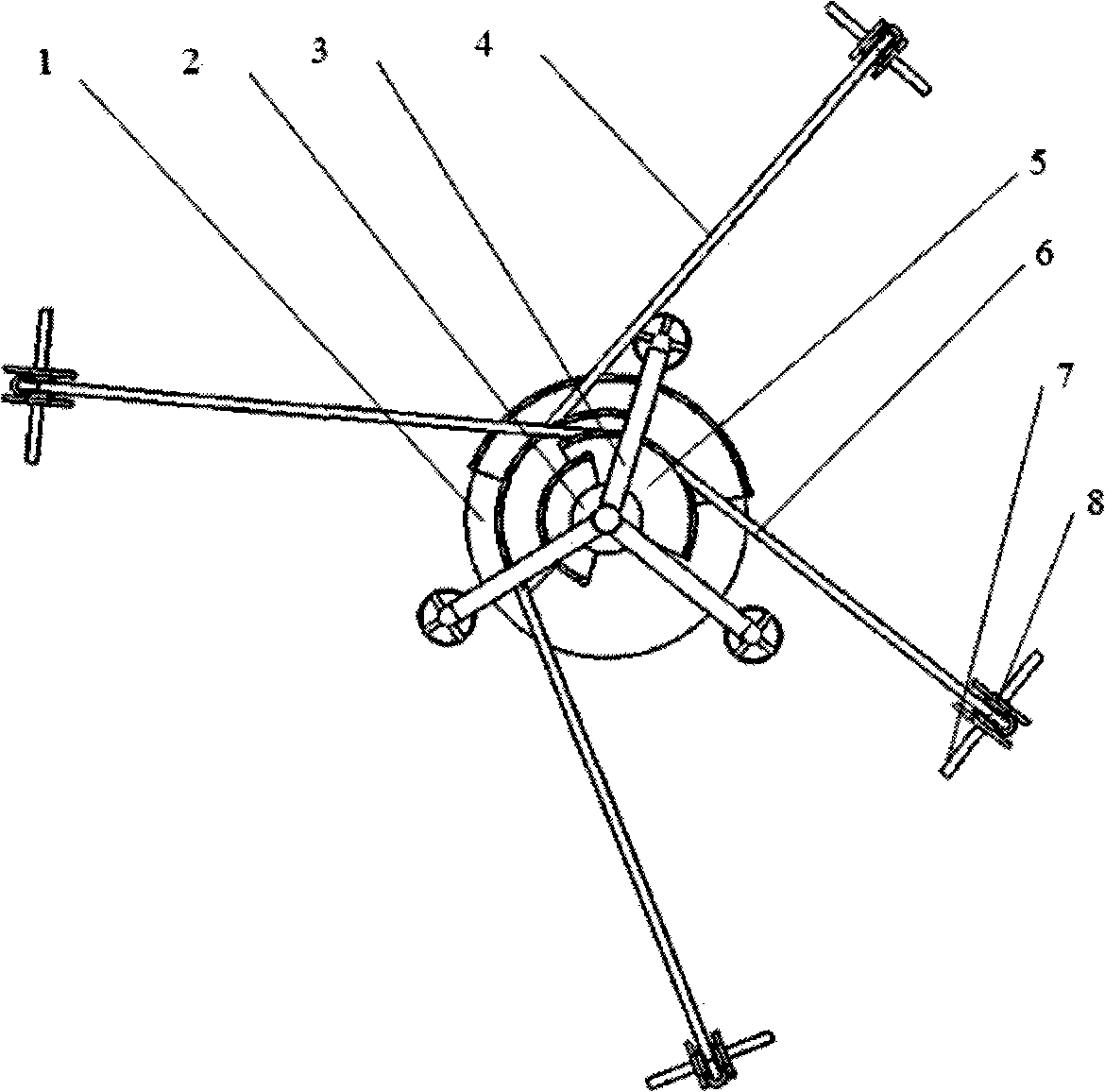
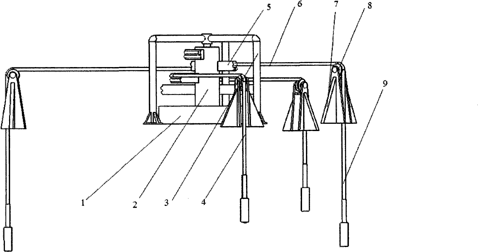
[0014] Such as figure 1 and figure 2 As shown, this embodiment includes: a drive unit 1, a rotating shaft 2, a support 3 and an oil pumping execution unit 4, wherein: one end of the rotating shaft 2 is connected to the driving unit 1, and the other end of the rotating shaft 2 is vertically and movably arranged in the support 3 , 2 pairs of oil pumping execution units 4 are connected with the rotating shaft 2, and the support 3 is fixedly arranged on the ground;

[0015] Each pair of oil pumping actuators 4 is symmetrically arranged on both sides of the rotating shaft 2 at 180 degrees.

[0016] The described oil...


PUM


Abstract

The invention provides a multiple well pumping unit in the technical field of geologic mining. The pumping unit comprises a drive unit, a rotating shaft, a support and pumping execution units, wherein one end of the rotating shaft is connected with the drive unit, while the other end is vertically and movably arranged in the support; a plural pairs of pumping execution units are connected with the rotating shaft; the support is fixed on the ground; and even pumping execution units are arranged, each pair of pumping execution units are symmetrically arranged on two sides of the rotating shaft at 180 degrees. The pumping unit doubles the working efficiency through pumping oil and gas at the same time by two strokes. A plurality of execution units can be fixedly connected on the rotating shaft to realize multiple well pumping.

Description

technical field [0001] The invention relates to a device in the technical field of geological mining machinery, in particular to a multi-well pumping unit. Background technique [0002] The most widely used in existing oilfields is the single-head single-well pumping unit, which pumps oil in the upstroke and does not work under no load in the downstroke. This kind of pumping unit occupies a large area, has complex devices and low system efficiency. [0003] After searching the prior art, it is found that Chinese Patent No. 01139505.2 discloses an "energy-saving pumping unit", which adopts a reciprocating lifting pumping mechanism, and has the characteristics of long stroke and high efficiency. However, its inlet position is located inside the frame, which makes it difficult to work over wells, and the maintenance workload of the transmission system is heavy, the reliability is not high, and the counterweight runs at high altitude without protection measures, so the safety i...

Claims


Application Information

Patent Timeline
Patent Type & Authority Patents(China)
IPC IPC(8): E21B43/00E21B19/02
Inventor 高峰张勇金振林赵现朝郭为忠陈杰
Owner SHANGHAI JIAOTONG UNIV
Why Eureka
Try Eureka