
Electric vacuum pump for automobile

A technology for electric vacuum pumps and automobiles, applied to pumps, parts of pumping devices for elastic fluids, pump components, etc., can solve the problems of easy damage, reduced service life of vacuum pumps, etc., to ensure service life and best braking effect good effect

Active Publication Date: 2011-10-05
ZHEJIANG ZHUJI WANBAO MASCH CO TLD
View PDF0 Cites 5 Cited by
  • Summary
  • Abstract
  • Description
  • Claims
  • Application Information

AI Technical Summary

Problems solved by technology

[0003] The purpose of the present invention is to provide an electric vacuum pump for automobiles, which can effectively solve the problem that the front end of the blade of the vacuum pump is easily damaged due to friction with the air inlet and outlet, and the service life of the vacuum pump is reduced.

Method used


Image

  • Electric vacuum pump for automobile
  • Electric vacuum pump for automobile
  • Electric vacuum pump for automobile

Examples


Embodiment Construction

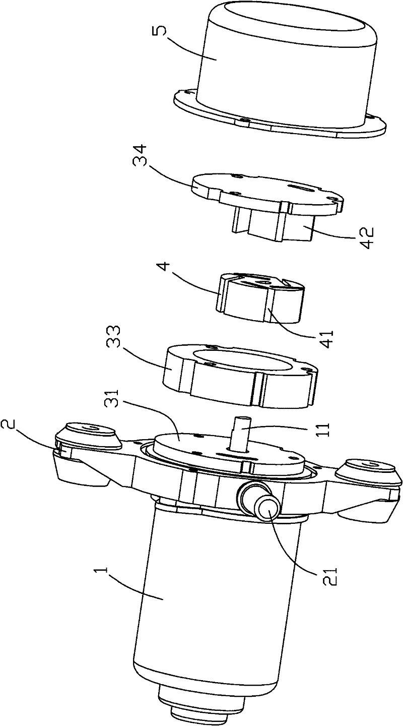
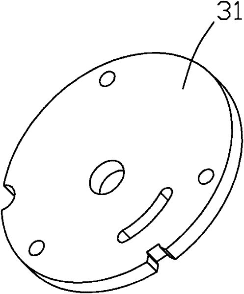
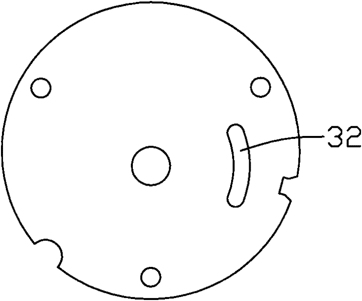
[0027] Such as Figure 1 to Figure 11 As shown, the electric vacuum pump for automobiles of the present invention includes a motor assembly 1, a housing 2, a stator assembly 3, a rotor 4 and a gland 5, and the housing 2 is provided with an air inlet 21 and an air outlet 22, and the stator assembly 3 It forms a radial eccentricity with the output shaft 11 of the motor assembly 1. The blade 42 is slidably connected to the rotor 4. The stator assembly 3 includes a stator seat 31, a stator 33 and a stator cover 34 in sequence. The air inlet slot 32 communicated with the air port 21 , the stator cover 34 is provided with an air outlet slot 35 communicated with the air outlet 22 of the housing 2 , and the axial width of the stator 33 corresponds to the vane 42 . The air intake slot 32 is arc-shaped, and the arc-shaped air intake slot 32 corresponds to the arc shape of the rotor 4 and is arranged at the outer circumference of the rotor 4 . The air outlet groove 35 is arc-shaped, and...


PUM


Abstract

The invention discloses an electric vacuum pump for an automobile. The pump comprises a motor assembly, a shell, a stator component, a rotor and a pressing cover, wherein the shell is provided with an air inlet and an air outlet; the stator component and an output shaft of the motor assembly form radial off-center; the rotor is in sliding connection with blades which can be driven to rotate in the stator component by the motor assembly; the shell and the pressing cover form a closed buffer cavity, and air enters the closed buffer cavity through the air inlet and is discharged from the air outlet; the stator component comprises a stator seat, a stator and a stator cover in sequence, the stator seat is provided with an air inlet slot communicated with the air inlet of the shell, and the stator cover is provided with an air outlet slot communicated with the closed buffer cavity and the air outlet of the shell; and the axial width of the stator corresponds to the blades. The pump can meetthe vacuum degree needed when the automobile brakes; and the motor assembly is connected with an external induction power supply, in braking, the power supply is connected so as to generate vacuum absorption force when the needed vacuum degree is reduced to a certain value, so that the pump is used for compensation when the vacuum degree needed to brake the automobile is not enough, and can make the automobile achieve the best braking effect.

Description

technical field [0001] The invention relates to an electric vacuum pump for automobiles. Background technique [0002] The vacuum pump is directly connected with the drive shaft of the engine (or with the alternator). When the vacuum suction is lower than a certain value, the drive shaft of the engine drives the rotor of the vacuum pump to run, and the air inhaled by the air inlet is compressed in the inner cavity of the pump. The air port is exhausted, thereby generating vacuum suction to provide for the work of automobile brakes. Such as Figure 12 Shown is the structural schematic view of the existing vane rotary vacuum pump, the inner wall of which is a cylindrical cylinder 91 is equipped with a cylindrical rotor 92, the cylinder is provided with an air inlet 93 and an air outlet 94, the rotor 92 The central axis is separated from the central axis of the cylinder 91 by a predetermined amount. Several vane grooves 95 are provided in the rotor 92 toward the central axis,...

Claims


Application Information

Patent Timeline
Patent Type & Authority Patents(China)
IPC IPC(8): F04C18/344F04C25/02F04C29/00
Inventor 朱哲剑傅永明边届鲍钱灿
Owner ZHEJIANG ZHUJI WANBAO MASCH CO TLD
Learn More