Pump unit
A technology of conveying unit and fuel pump, applied in the direction of engine components, charging system, machine/engine, etc., can solve problems such as increasing the cost of conveying unit
- Summary
- Abstract
- Description
- Claims
- Application Information
AI Technical Summary
Problems solved by technology
Method used
Image
Examples
Embodiment Construction
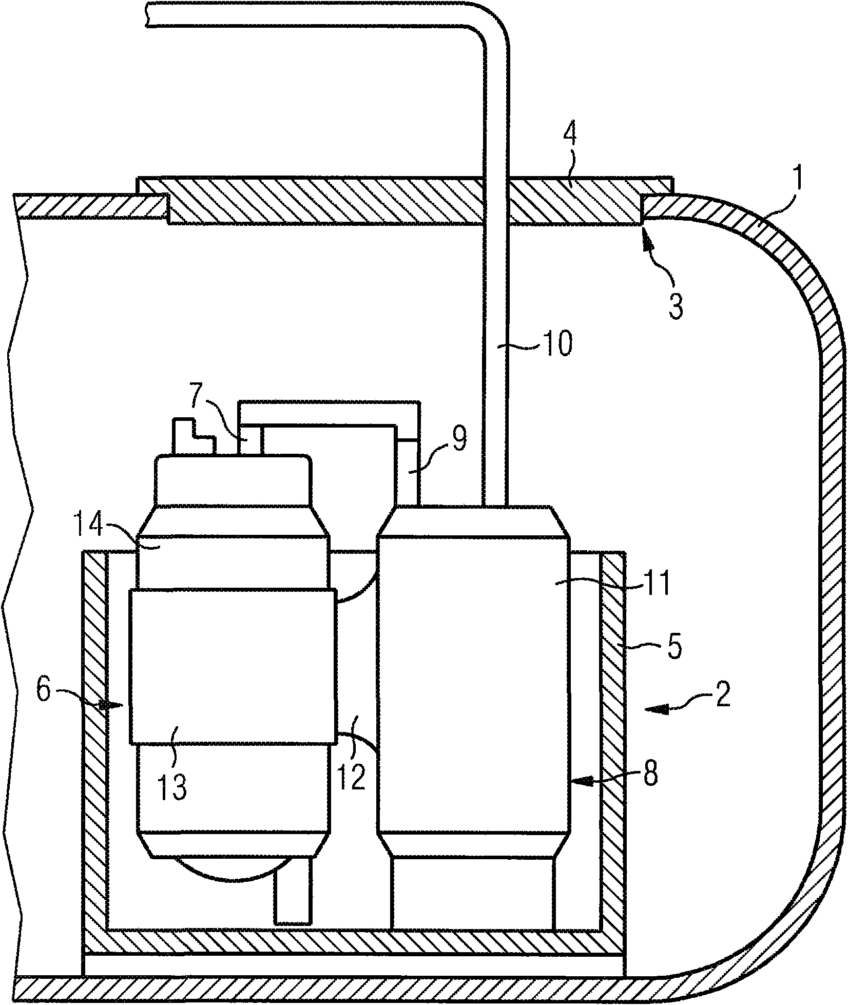
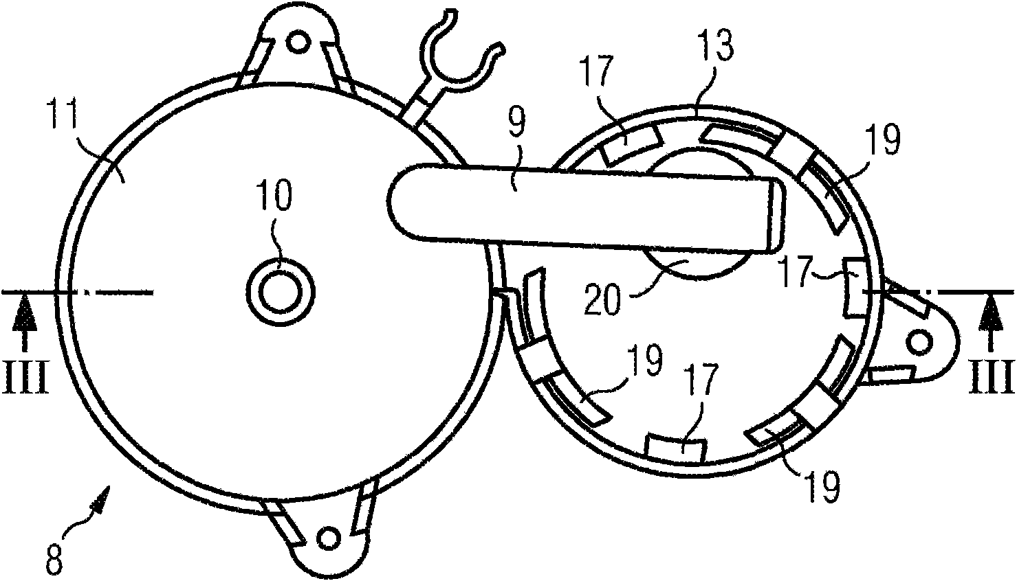
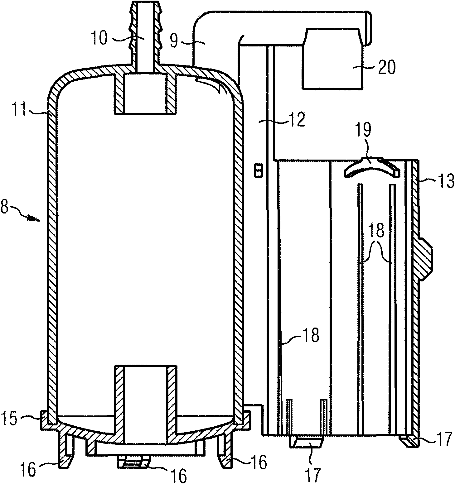
[0015] figure 1 A fuel tank 1 of a motor vehicle (not shown further) is shown, which has a delivery unit 2 which is inserted through an opening 3 in the fuel tank 1 . After assembly, the opening 3 is closed with the flange 4 . The delivery unit 2 comprises a swirl pot 5 which is prestressed with respect to the bottom of the fuel tank 1 . Arranged in the swirl pot 5 is a fuel pump 6 which sucks the fuel out of the swirl pot 5 and conveys it through the discharge sleeve 7 . In addition, a fuel filter 8 is also arranged in the anti-swirl tank 5, which is arranged downstream of the fuel pump 6 from the flow direction, so that the fuel delivered by the fuel pump 6 passes through the input sleeve 9 to reach the fuel filter. device 8. The filtered fuel then flows via a feed line 10 via flange 4 to a motor vehicle internal combustion engine (not shown). The housing 11 of the fuel filter 8 has a one-piece injection-molded web 12 which is integrated into a pump holder 13 . In the p...
PUM
 Abstract
Description
Claims
Application Information
 - R&D
- Intellectual Property
- Life Sciences
- Materials
- Tech Scout
- Unparalleled Data Quality
- Higher Quality Content
- 60% Fewer Hallucinations
Browse by: Latest US Patents, China's latest patents, Technical Efficacy Thesaurus, Application Domain, Technology Topic, Popular Technical Reports.
© 2025 PatSnap. All rights reserved.Legal|Privacy policy|Modern Slavery Act Transparency Statement|Sitemap|About US| Contact US: help@patsnap.com


