
Bidirectional final motion test fixture and bidirectional final motion test method thereof

A test fixture and fixture technology, which is applied in the application of repetitive force/pulsation force to test the strength of materials, test wear resistance, measuring devices, etc., can solve problems such as coating life evaluation, and achieve the effect of small error and accurate displacement measurement.

Inactive Publication Date: 2010-12-29
SOUTHWEST JIAOTONG UNIV
View PDF5 Cites 0 Cited by
  • Summary
  • Abstract
  • Description
  • Claims
  • Application Information

AI Technical Summary

Problems solved by technology

However, the existing micro-movement test fixture clamps the plane specimen and the hydraulic loading direction (that is, the simulated micro-motion direction) of the hydraulic servo test bench is either perpendicular or parallel, so only a single tangential or radial micro-motion test can be performed. However, it is impossible to conduct tangential and radial two-way fretting experiments, so that the tribological properties of materials under the conditions of a large number of bidirectional fretting conditions cannot be truly and accurately tested and the evaluation of coating life

Method used

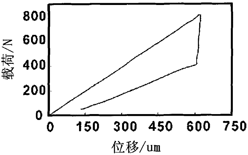
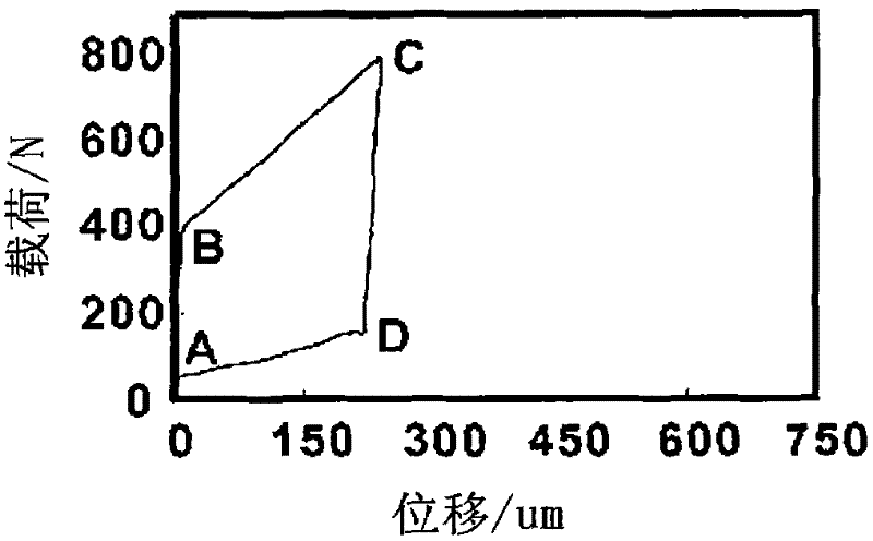

Image

  • Bidirectional final motion test fixture and bidirectional final motion test method thereof
  • Bidirectional final motion test fixture and bidirectional final motion test method thereof
  • Bidirectional final motion test fixture and bidirectional final motion test method thereof

Examples


Embodiment approach

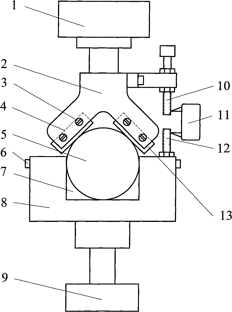
[0038] figure 1 As shown, the first specific embodiment of the present invention is a two-way micro-motion test fixture, including: a plane specimen fixture 2 threaded to the lower part of the load sensor 1 under the beam of the hydraulic servo micro-motion test bench, and a hydraulic servo micro-motion test fixture 2. The ball specimen fixture 8 that is threaded on the piston 9 of the hydraulic cylinder of the test bench. in:

[0039] The plane test piece fixture 2 is in the shape of a "herringbone", and the opposite surfaces on the left and right sides of the bottom of the plane test piece fixture 2 are provided with grooves 4 that are compatible with the plane test piece 13, and on the walls of the groove 4 are provided The screw 3 of the tight plane test piece 13;

[0040] The ball test piece fixture 8 is provided with the ball test piece cavity 7 that is compatible with the ball test piece 5, and the wall of the ball test piece cavity 7 is provided with a screw 6 for t...

Embodiment 2

[0051] The bidirectional fretting test fixture of this embodiment is exactly the same as that of Embodiment 1.

[0052] Its experimental method is also basically the same as Example 1, and the difference is only the following two operations:

[0053] A. Test piece installation: place two plane test pieces 13 in the grooves on both sides of the plane test piece fixture 2 .

[0054] D. Micro-motion experiment: the load sensor 1 data is cleared, the computer measurement and control system controls the piston 9 to move the ball specimen fixture 8 upward according to the set loading speed, and applies a load to the plane specimen 13, so that the ball specimen 5 is pressed into the plane The test piece 13 reaches the set depth; then the piston 9 reciprocates up and down with the set displacement amplitude centered on the position of the depth, and the displacement amplitude is less than twice the set depth value; the piston 9 reciprocates to The set number of cycles; while the pist...


PUM

PropertyMeasurementUnit
angleaaaaaaaaaa

Abstract

The invention relates to a bidirectional micro motion test fixture and a bidirectional micro motion test method thereof. The fixture is mainly in the structure that: a planar test-piece fixture (2) is in an inversed V shape, the opposite surfaces of the left and right sides of the lower part are all opened with a groove (4) fit to a planar test-piece (13), and the wall of the groove (4) is provided with a puller screw (3); a spherical test-piece fixture (8) is opened with a spherical test-piece cavity (7) fit to a spherical test-piece (5), and the wall of the spherical test-piece cavity (7) is provided with a puller screw (6); and the vertical axes of the spherical test-piece cavity (7), a piston (9) and the planar test-piece fixture (2) are coincided. One side of the upper part of the planar test-piece fixture (2) is connected with an upper vertical screw (10) while the spherical test-piece fixture (8) is connected with a lower vertical screw (12), and a displacement sensor is connected with the upper vertical screw (10) and the lower vertical screw (12). The test fixture can effectively simulate bidirectional fretting under spherical / surface contact condition, test tribology properties and estimate contact fatigue life of a coating under spherical / surface bidirectional micro motion condition on the existing hydraulic servo micro motion test platform.

Description

technical field [0001] The invention relates to the technical field of material friction and wear performance and coating life evaluation test, in particular to a material fretting test method and a fretting test fixture. Background technique [0002] Different from friction methods such as sliding and rolling, fretting is a relative movement with extremely small amplitude (usually on the order of microns) between tight fitting parts. The movement mode of fretting is very complicated. Taking the contact between a ball and a plane as an example, according to different relative motion directions, fretting can be divided into four basic types: tangential type, radial type, rolling type and twisting type. The fretting direction of the radial fretting is the tangential direction of the spherical surface at the ball / surface contact, and the fretting direction of the radial fretting is the normal direction of the spherical surface at the ball / surface contact. Fretting can cause su...

Claims


Application Information

Patent Timeline
Patent Type & Authority Patents(China)
IPC IPC(8): G01N3/04G01N3/56G01N3/36G01N19/04
Inventor 朱旻昊蔡振兵周仲荣莫继良刘启跃石心余
Owner SOUTHWEST JIAOTONG UNIV
Learn More