Motor end cover component

A technology for motor end caps and components, which is applied to electric components, electrical components, electromechanical devices, etc., can solve problems such as end cap waste

Inactive Publication Date: 2009-12-23
JOHNSON ELECTRIC SHENZHEN
View PDF0 Cites 10 Cited by
  • Summary
  • Abstract
  • Description
  • Claims
  • Application Information

AI Technical Summary

Problems solved by technology

However, different applications may require motor leads extending in different directions
In this way, if the extension direction of the lead-out wire needs to be changed, the end cover and the lead-out wire fixing structure need to be replaced, resulting in waste of the end cover

Method used


Image

  • Motor end cover component
  • Motor end cover component
  • Motor end cover component

Examples


Embodiment Construction

[0017] In order to make the technical problems to be solved, technical solutions and beneficial effects of the present invention clearer, the present invention will be further described in detail below in conjunction with the accompanying drawings and embodiments. It should be understood that the specific embodiments described here are only used to explain the present invention, not to limit the present invention.

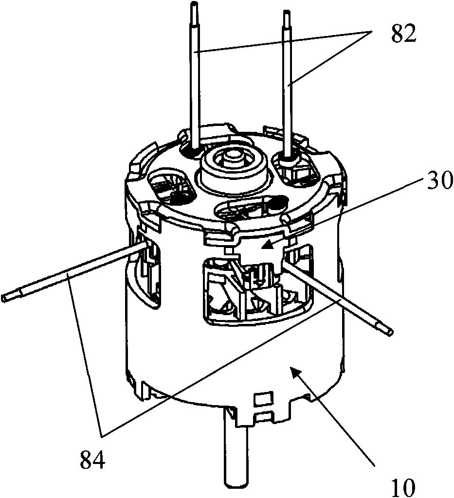
[0018] figure 1 The above is a schematic structural diagram of the motor end cover assembly installed on the motor 10 provided by an embodiment of the present invention. The motor end cover assembly includes: an end cover 30 installed at one end of the motor 10 , a pair of motor lead wires 82 extending along the motor axial direction, and a pair of motor lead wires 84 extending along the motor radial direction.

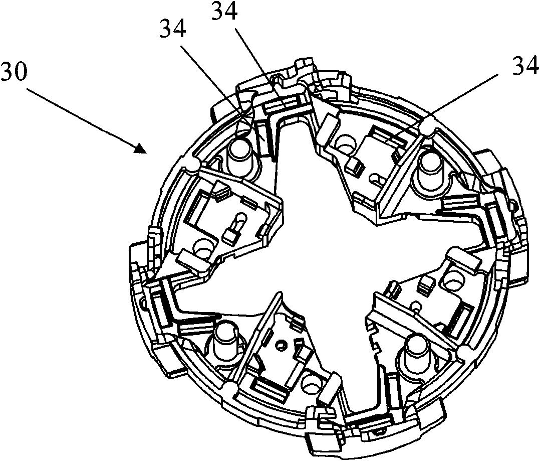
[0019] see figure 2 , the end cover 30 is provided with a plurality of button holes 34 .

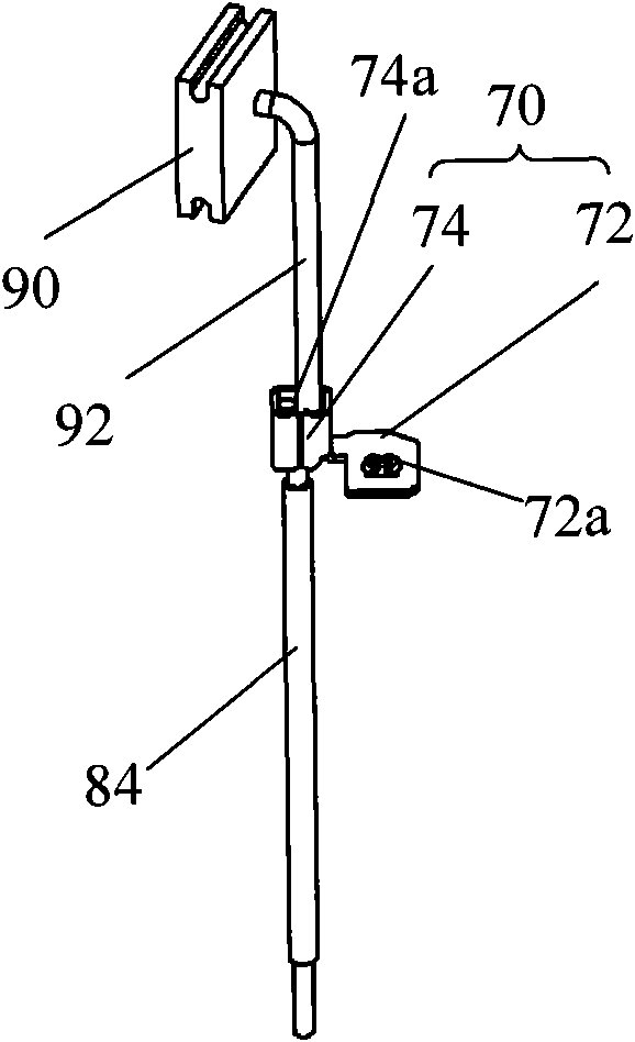
[0020] see Figure 3A and Figure 3B , The motor end cove...


PUM


Abstract

The invention provides a motor end cover component, which comprises an end cover, an electric brush fixed frame arranged on the end cover, an electric brush arranged on the fixed frame in a sliding way, motor leading-out wires and a brush braid of which one end is fixed with the electric brush, wherein the fixed frame comprises a fixation part capable of selectively fixing at least two connectingmembers; the at least two connecting members are provided with clamping grooves which extend along different directions and are used for clamping the motor leading-out wires and the other end of the brush braid of the electric brush so that the motor leading-out wires are electrically connected with the electric brush through the brush braid. For the motor end cover component, because the same end cover and the same fixed frame can be provided with different types of the connecting members of the clamping grooves extending along the different directions, the motor leading-out wires extending along the different directions can be obtained.

Description

technical field [0001] The invention relates to the field of motors, in particular to a motor end cover assembly. Background technique [0002] Typically, a permanent magnet DC motor uses a commutator and brushes to transfer electrical power to the armature, causing the armature to rotate. Generally, the brushes are fixed near the commutator by an end cap so as to make contact therewith. [0003] Figure 8A and Figure 8B show the motors of the prior art. It can be seen from the figures that in the motors of the prior art, one end cover can only fix the lead wires in one direction, as shown in Figure 8A, through the lead wire fixing structure. The lead-out wire 2 to the end cover 3 extends radially along the motor, and in FIG. 8B , the lead-out wire 4 fixed to the end cover 3' extends along the axial direction of the motor. However, different applications may require motor leads extending in different directions. In this way, if the extension direction of the lead-out wire ...

Claims


Application Information

Patent Timeline
IPC IPC(8): H02K5/04H02K5/14H02K5/22
Inventor 刘清式黄耀龙金昌林
Owner JOHNSON ELECTRIC SHENZHEN
Why Eureka
Try Eureka