Woven aortic sinus prosthesis having a bulb

A technology for aortic sinus and sinus sham, applied in prosthesis, textiles and papermaking, devices with tubular structure of human body, etc., can solve the problems of complex weaving technology and no additional structure

Inactive Publication Date: 2013-09-18
AESCULAP AG
View PDF6 Cites 0 Cited by
  • Summary
  • Abstract
  • Description
  • Claims
  • Application Information

AI Technical Summary

Problems solved by technology

The disadvantage of these types of vascular prostheses is that they do not have an additional structure that can in particular replace the function of the aortic sinus removed during surgery
Producing this prosthesis requires complex weaving techniques

Method used


Image

  • Woven aortic sinus prosthesis having a bulb
  • Woven aortic sinus prosthesis having a bulb
  • Woven aortic sinus prosthesis having a bulb

Examples


Embodiment Construction

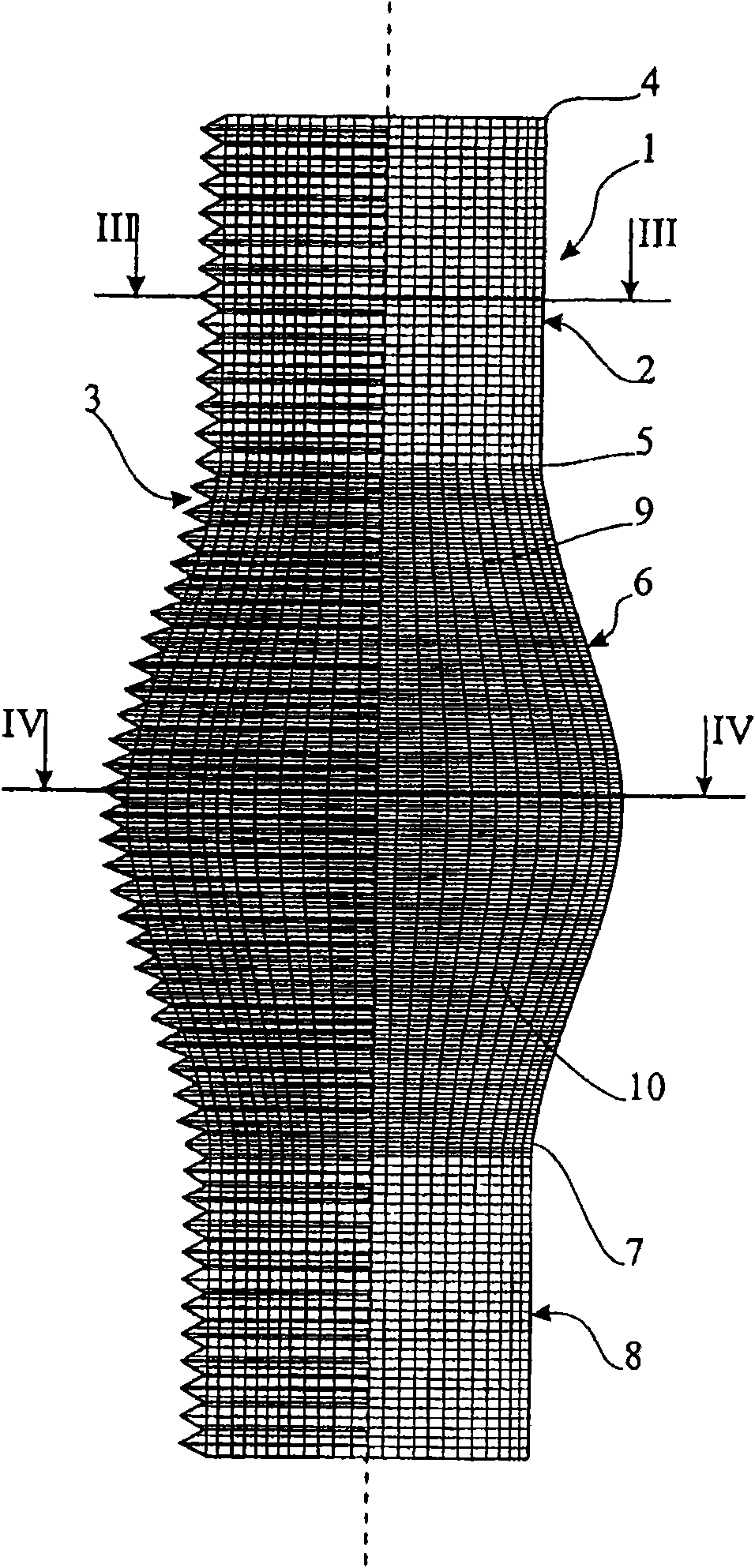
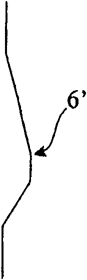
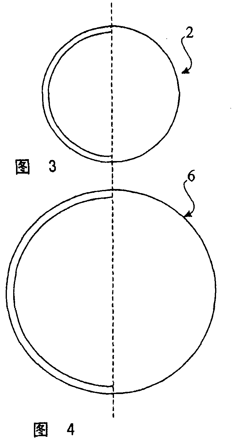
[0054] exist figure 1 , image 3 and Figure 4 In the illustrated embodiment, the woven aortic sinus prosthesis 1 has a portion 2 not close to the heart, which is shaped cylindrically except for a transverse folded portion 3 . The portion 2 that is not close to the heart can enter at its upper end 4 seamlessly or by means of a transverse seam into the aortic arch, which is not shown in the figure. The portion 2 of the aortic sinus prosthesis that is not close to the heart enters at its lower end 5 axially and seamlessly into the bulbous portion 6 . When viewed in the circumferential direction, the spherical portion 6 can be uniformly ( figure 1 and Figure 4 ) or unevenly ( Figure 5 ) to extend. The spherical part 6 also has a transverse corrugated part 3 . A substantially cylindrical portion 8 close to the heart is also connected axially and seamlessly to the lower end 7 of the spherical portion 6 , said portion 8 being likewise cylindrically shaped except for the tra...


PUM

PropertyMeasurementUnit
lengthaaaaaaaaaa
lengthaaaaaaaaaa
lengthaaaaaaaaaa

Abstract

A first cylindrical section (2) away from a heart verges into an aortic curve, if required. A second cylindrical section (6) has a wider diameter compared to the first section, forms a bulbus and links to the first section. If required, a third cylindrical section (8) near to a heart links to the section forming the bulbus.

Description

technical field [0001] The present invention relates to a woven aortic sinus prosthesis. Background technique [0002] Replacement of the aortic region close to the heart, especially the so-called ascending aortic region, is one of the most important specialties in the field of modern cardiac surgery. A variety of vascular prostheses have been developed to achieve the above objectives. These vascular prostheses are usually implanted after removal of the aneurysmatic portion of the ascending aorta, and specifically after removal of the aortic sinus (natural sinus) while maintaining the aortic valve and arterial wall Some cases are implanted. [0003] Early vascular prostheses were straight and homogeneous tubular prostheses. A disadvantage of these types of vascular prostheses is that they do not have an additional structure which in particular can replace the function of the aortic sinus removed during surgery. Therefore, they cannot adequately correspond to the actual a...

Claims


Application Information

Patent Timeline
Patent Type & Authority Patents(China)
IPC IPC(8): A61F2/06D03D3/02D03D3/06
CPCA61F2250/0039A61F2/06D03D3/02D03D3/06A61F2250/0017D03D13/004D03D13/008D06M10/008D06M15/15D10B2509/06D03D15/49
Inventor H·戈尔德曼C·默克尔H·-H·西弗斯
Owner AESCULAP AG
Why Eureka
Try Eureka