Micro slip control method during lock-up meshing of wet clutch

A wet clutch and control method technology, applied in the field of control, can solve the problems of increased fuel consumption, large shift shock, large energy loss, etc., and achieve the effects of improving reliability and service life, reducing shift shock, and small energy loss

Inactive Publication Date: 2009-12-30
SAIC MOTOR +1
View PDF0 Cites 23 Cited by
  • Summary
  • Abstract
  • Description
  • Claims
  • Application Information

AI Technical Summary

Problems solved by technology

Moreover, due to the uncertainty of the dynamic variable friction coefficient in the formula, it is difficult to ensure that the clutch is fully engaged. If unnecessary slip occurs during driving, it will reduce the life and reliability of the wet clutch, which will negatively affect the advantages of the wet clutch. effect, and this method has a large impact on shifting gears, which reduces the driving comfort of the vehicle
[0012] There are also a few foreign literatures that propose to solve the problem of insufficient meshing that may occur through the control method of additional force (Surplus Pressure), that is, to add a certain amount of force on the basis of the theoretical results of the above formula, but under this control, the oil pump in the hydraulic system is for Additional work is required to generate additional force, which will cause greater energy loss, thereby increasing fuel consumption and reducing the economy of the vehicle
Moreover, the additional force is easy to completely discharge the oil film that is conducive to friction from the friction pair, and then a large friction is likely to occur at the moment when the clutch is released from sliding friction, which affects the service life of the wet clutch

Method used


Image

  • Micro slip control method during lock-up meshing of wet clutch
  • Micro slip control method during lock-up meshing of wet clutch
  • Micro slip control method during lock-up meshing of wet clutch

Examples


Embodiment Construction

[0031] The micro-slip friction control method of the present invention when the wet clutch is locked and engaged will be described in detail below with reference to the accompanying drawings.

[0032] Aiming at the deficiencies and defects of the existing control strategies, the present invention proposes a strategy of micro-slip friction control clutch lock-up and engagement.

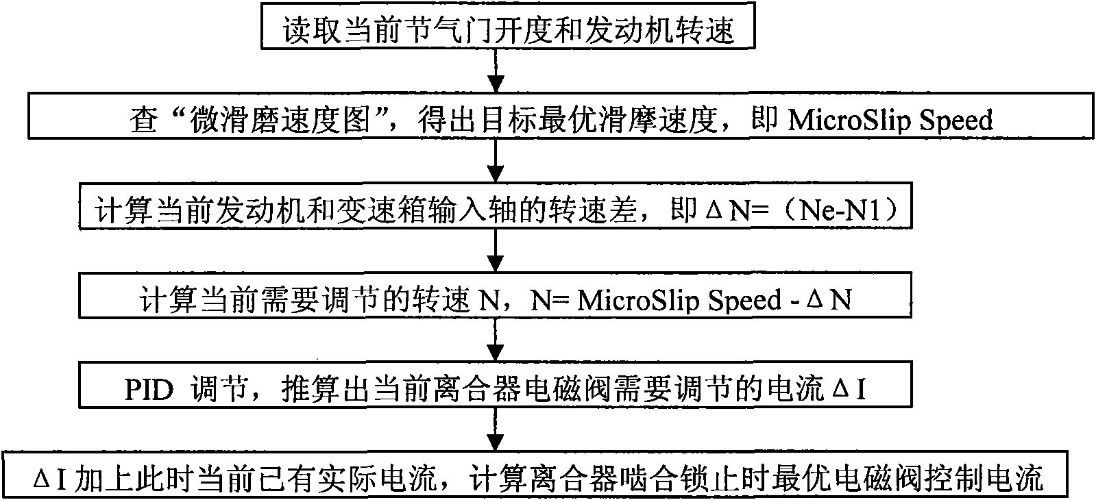
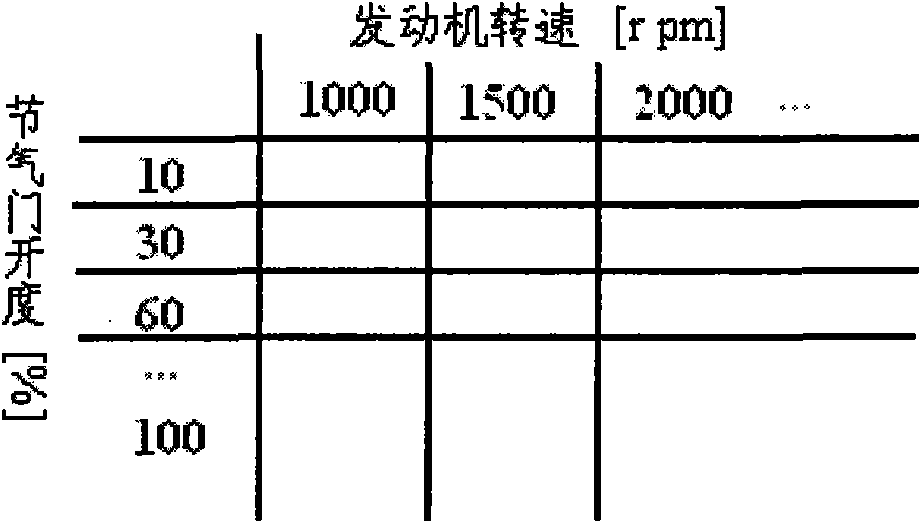
[0033] Micro-slip speed is a dynamic quantity, mainly determined by the current throttle opening and engine speed. Before designing the control strategy, it is necessary to conduct theoretical calculations and a large number of experiments on the wet clutch used to obtain the following: image 3 and Figure 4 The microslip friction velocity diagram shown. When actually driving, according to the current throttle opening and the engine speed, look up the table to obtain the optimal sliding speed, as a reference in the strategy, and then calculate the optimal current of the output solenoid valve, so as ...


PUM


Abstract

The invention discloses a micro slip control method during lock-up meshing of a wet clutch, including: firstly, reading current throttle percentage and engine speed; secondly, looking up a micro slip speed diagram to obtain optimal micro slip speed namely MicroSlip Speed; thirdly, calculating the current rotating speed difference between the engine and the input shaft of a gear reducer; fourthly, calculating the current rotating speed N required to be regulated; fifthly, converting the rotating speed difference into corresponding current variation value, namely the current delta I required to be regulated to control relevant solenoid valve of the clutch, through appropriate PID regulation; sixthly, adding the current delta I of solenoid valve required to be regulated the clutch with the current existing effective current and calculating optimal control current of the solenoid valve during micro slip lock-up meshing of the clutch. The invention can effectively reduce shift impact, reduce oil consumption in frequent shift process and can obviously improve operation reliability of the clutch and prolong the service life of the clutch.

Description

technical field [0001] The invention relates to a control method, in particular to a micro-slip friction control method applied to a wet clutch of an automobile engine and a transmission when locking and engaging. Background technique [0002] The so-called wet clutch refers to the friction contact surface of the clutch friction plate during the sliding friction process, which is the friction of the liquid and semi-liquid interface. Compared with the traditional dry clutch, it has a qualitative change, that is, when sliding, the friction surface There is no direct contact, and the two friction surfaces are separated by a thin layer of oil film with a thickness of about 0.1mm. Wear and stable friction coefficient, and the rupture of the oil film during the friction process will increase the wear sharply. Therefore, compared with the dry clutch, the control of the wet clutch has stricter technical requirements and is more complicated and difficult. [0003] In the traditional...

Claims


Application Information

Patent Timeline
Patent Type & Authority Applications(China)
IPC IPC(8): F16D48/06
Inventor 黄明礼李育黄文华卢建钢陈洁婧姜超张轶
Owner SAIC MOTOR
Why Eureka
Try Eureka