A Method of Using Random Array to Realize the Focusing of Reverberation Sound Field
A technology of random array and reverberation sound field, applied in the direction of sound-generating equipment, instruments, etc.
- Summary
- Abstract
- Description
- Claims
- Application Information
AI Technical Summary
Problems solved by technology
Method used
Image
Examples
Embodiment 1
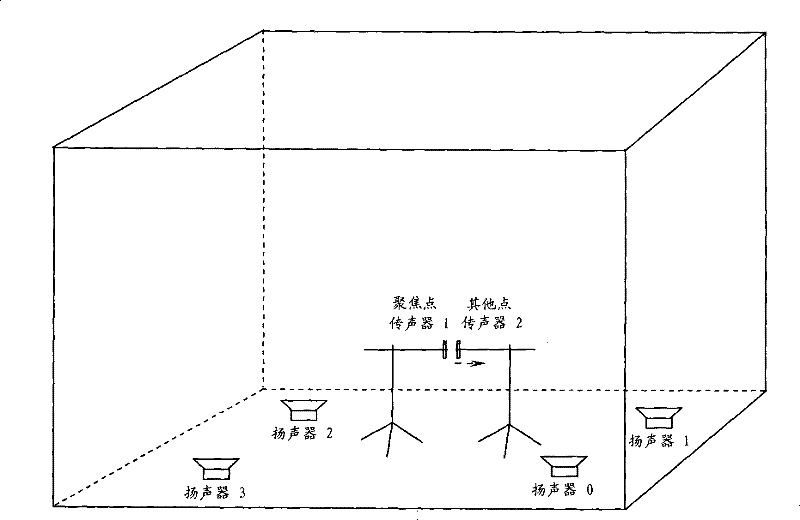
[0070] In this embodiment, as figure 1 As shown, on the ground of the reverberation room (length 5.1m, width 4.9m, height 4.0m), 4 speaker units with a power of 20W are randomly placed to form an array, and a microphone unit is placed at the desired focus point for Measure the received signal at the desired point, place another microphone directly in front of the focus point, and move the position of the microphone forward at an interval of 3 cm to measure the focus signal at other locations other than the desired location point. Use the Pulse instrument of the Danish B&K company to record the received signals collected by the two microphones, and write the code on the matlab software of the PC to realize the time domain inversion and amplitude amplification of the received signal recorded by the Pulse instrument corresponding to the desired focus point .
[0071] The specific implementation process of this embodiment includes the following steps:
[0072] 1) First set the sampli...
Embodiment 2
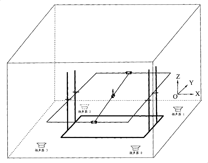
[0079] In this embodiment, as figure 2 As shown, 4 loudspeaker units are randomly placed on the floor of the reverberation room, and the single-period sine pulse signals with frequencies of 600 Hz, 1000 Hz, and 3000 Hz are mixed in a 4-element random array according to the three steps described in Example 1. Sound field focusing experiment.
[0080] When the microphone unit slides along the X-axis, Y-axis and Z-axis at 3cm intervals, the sound pressure peaks of the focus signals corresponding to these three frequency source signals are measured with the distance difference on the three coordinate axes (the position of the microphone) And the desired focus point). Picture 10 , 11 And 12 respectively give the normalized distribution curves of the peak sound pressure of the focus signal corresponding to the source signal with frequencies of 600 Hz, 1000 Hz, and 3000 Hz on the X-axis, Y-axis and Z-axis.
[0081] Comparing these curves, it can be seen that the spatial scale of the foc...
Embodiment 3
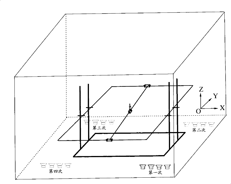
[0083] In this embodiment, as image 3 As shown, in the reverberation room, the 4-element line arrays are respectively placed at the locations of the 4 speaker units mentioned in Example 2. Also in accordance with the three steps described in Example 1, at these 4 locations The four-element linear array reverberation sound field focusing experiments were performed on single-period sine pulse signals with frequencies of 600 Hz, 1000 Hz, and 3000 Hz, respectively, and the reverberation sound field focusing experimental results of the 4-element linear array and the 4-element random array were compared.
[0084] When the microphone unit slides along the X-axis, Y-axis and Z-axis at 3cm intervals, the sound pressure peaks of the focus signals corresponding to these three frequency source signals are measured with the distance difference on the three coordinate axes (the position of the microphone) And the desired focus point). Figure 13 , 14 And 15 are when the linear array is placed ...
PUM
 Abstract
Description
Claims
Application Information
 - R&D
- Intellectual Property
- Life Sciences
- Materials
- Tech Scout
- Unparalleled Data Quality
- Higher Quality Content
- 60% Fewer Hallucinations
Browse by: Latest US Patents, China's latest patents, Technical Efficacy Thesaurus, Application Domain, Technology Topic, Popular Technical Reports.
© 2025 PatSnap. All rights reserved.Legal|Privacy policy|Modern Slavery Act Transparency Statement|Sitemap|About US| Contact US: help@patsnap.com


