
Remaining needle sleeve head forming machine

A technology of indwelling needles and molding machines, which is applied in the field of processing machinery for medical equipment, can solve problems such as low efficiency, high labor intensity of inspectors, and poor head taper effect, so as to improve molding efficiency, reduce inspection work intensity, and ensure molding effect of effect

Inactive Publication Date: 2010-01-06
常熟市尚湖镇高科科技设备厂
View PDF0 Cites 3 Cited by
  • Summary
  • Abstract
  • Description
  • Claims
  • Application Information

AI Technical Summary

Problems solved by technology

[0004] The indwelling needle cannula head forming machine with the above structure is difficult to ensure the molding quality and the ideal pass rate when molding the indwelling needle cannula head, because it is difficult for the indwelling needle cannula head to be formed in a hot state after entering the mold 62. The mold cavity of the mold 62 fully removes the burrs left on the head during the processing of the cannula of the indwelling needle, and even if the burrs are removed, the taper effect of the head is poor, so it cannot be used clinically.
In order to ensure the effect of clinical use, the manufacturer can only strictly control the inspection, and manually inspect the formed indwelling needle cannula under a magnifying glass without any leakage. Moreover, the labor intensity of inspectors is high
On the other hand, due to the low pass rate, which is only about 50-60%, it causes serious waste, which not only causes resource loss, but also leads to increased production costs.

Method used


Image

  • Remaining needle sleeve head forming machine
  • Remaining needle sleeve head forming machine
  • Remaining needle sleeve head forming machine

Examples


Embodiment 1

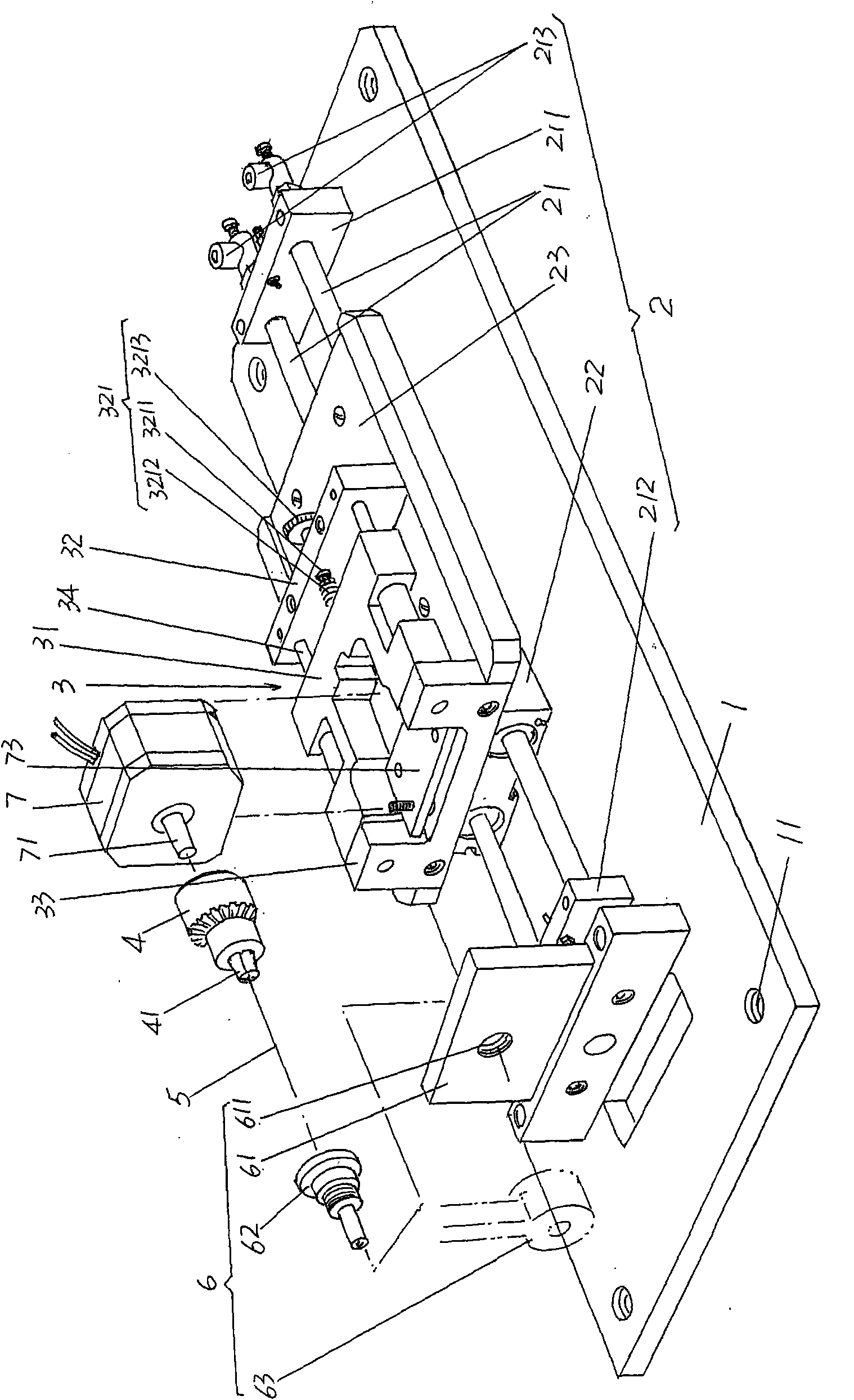
[0023] please see figure 1 , image 3 and Figure 4 , a rectangular base 1 that is a rectangle is provided, and when the present invention is in an applied state, the base 1 is fixed with a separately configured machine base through the screw holes 11 thereon. A fixture driving mechanism 2 is disposed on the base 1, preferably but not absolutely limited to the structure of the fixture driving mechanism 2 is as follows, a pair of air ducts 21 are parallel to each other, and one end of each is fixed on the first conduit seat 211, and each The other end is fixed on the second catheter adapter 212, the first and second catheter adapters 211, 212 are both fixed to the base 1, and the two keep corresponding. At one end of a pair of air ducts 21 figure 1 The right ends shown are respectively equipped with air inlet and outlet ports 213, and the pair of air inlet and outlet ports 213 are connected with an air source device by an air source pipeline, such as an air compressor or s...

Embodiment 2

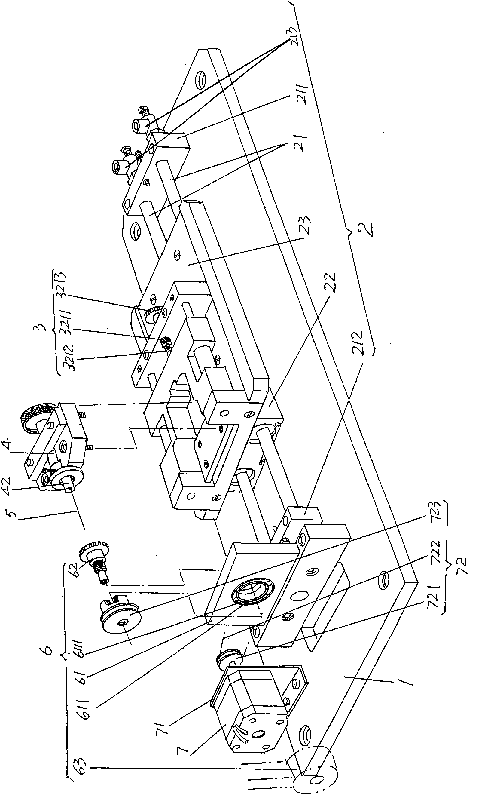
[0028] please see figure 2 , embodiment 1 is to make the mandrel 5 rotate, and the present embodiment is to make the mold 62 rotate, and the mandrel clamp 4 is directly installed on the movable seat body 31 of the clamp movable seat 3 (embodiment 1 is installed on the motor shaft of the motor 7 71, and the motor 7 is installed on the movable seat body 31), the mandrel 5 is fixed on the mandrel holder 42 of the mandrel clamp 4, and the mandrel holder 42 is equivalent to the three-jaw chuck 42 of embodiment 1. The bearing 6111 is arranged in the mold positioning hole 611 provided in the upper central part of the mold holder 61, and the motor 7 is fixed on the left end of the base 1 through an L-shaped support, and the power is transmitted to the aforementioned taper forming mechanism by the transmission device 72 The mold 62 of 6, that is, to make the mold 62 rotate, specifically: fix the first pulley 721 on the motor shaft 71 of the motor 7, fix the second pulley 723 in the fo...


PUM


Abstract

The invention relates to a remaining needle sleeve head forming machine, belonging to the field of processing mechanical technology of medical equipment. The forming machine comprises a base, a clamp driving mechanism which is arranged on the base, a clamp sliding seat which is arranged on the clamp driving mechanism, a core rod clamp, a core rod arranged on the core rod clamp and a conical degree forming mechanism which is arranged on the base, corresponds to the core rod and is composed of a fixed base, a mold and a heating head. The forming machine is characterized in that: the forming machine also comprises a motor which is arranged on the clamp sliding seat, and the core rod clamp is fixedly arranged on the motor shaft of the motor and corresponds to the mold. The forming machine has the advantages that the forming effect is ensured and the passing percent is improved more than 98 percent, the forming efficiency is improved and the inspection working strength of the inspectors is reduced in the following inspection.

Description

technical field [0001] The invention belongs to the technical field of processing machinery for medical equipment, and in particular relates to a molding machine for the head of an indwelling needle sleeve. Background technique [0002] The indwelling needle is also used to be called a trocar, because the indwelling needle has good flexibility, long indwelling time in the vein and is not easy to break through the blood vessel wall, which is beneficial to reduce the pain caused by repeated punctures and protect the blood vessels. It also has the characteristics of being convenient for clinical medication, emergency rescue and reducing the workload of medical staff, especially nursing staff, so it has been widely used in clinical practice in recent years. [0003] As can be seen from the above description, the so-called indwelling needle is to send the cannula into the vein by the needle or needle body, and after the needle is removed, the cannula is left in the vein. The pro...

Claims


Application Information

Patent Timeline
Patent Type & Authority Applications(China)
IPC IPC(8): B29C43/02B29C43/32
Inventor 陶岳明
Owner 常熟市尚湖镇高科科技设备厂
Learn More