Oil-water separating sewage drain device for transformer oil reservoir

A sewage device, oil-water separation technology, applied in the direction of liquid separation, separation methods, chemical instruments and methods, etc., can solve the problems of increasing the work intensity of operation and maintenance personnel, increasing the cost of equipment operation and maintenance, and pollution of the surrounding environment, so as to reduce patrol work The effect of reducing the amount of work, eliminating potential safety hazards, and reducing workload

Inactive Publication Date: 2017-02-22
YANTAI POWER SUPPLY COMPANY OF STATE GRID SHANDONG ELECTRIC POWER +1
View PDF5 Cites 3 Cited by
  • Summary
  • Abstract
  • Description
  • Claims
  • Application Information

AI Technical Summary

Problems solved by technology

Since the sewage outlet of the oil storage tank is generally designed to be located 50cm above the bottom, there will be accumulated water in the oil storage tank, especially in the flood season and thunderstorm weather, there will be a large amount of accumulated water in the oil storage tank, and only when the water level exceeds 50cm will it be drained. It will be discharged through the sewage outlet, but the accumulated water below the water level of 50cm cannot be discharged. If the accumulated water is not discharged in time, when a transformer accident or other reasons occur during this period, the transformer oil will flow out through the sewage outlet, which will affect the surrounding environment. cause serious pollution
Therefore, the oil storage tank needs frequent inspection and manual drainage by the operation and maintenance personnel to ensure that the transformer oil storage tank plays a role in the event of a transformer oil leakage accident, which not only increases the work intensity of the operation and maintenance personnel, but also increases the equipment operation and maintenance. cost

Method used


Image

  • Oil-water separating sewage drain device for transformer oil reservoir
  • Oil-water separating sewage drain device for transformer oil reservoir
  • Oil-water separating sewage drain device for transformer oil reservoir

Examples


Embodiment

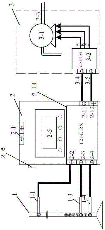
[0024] Embodiment: A kind of oil-water separation and sewage discharge device of transformer oil storage pool (see figure 1 ), which consists of three parts: oil storage tank water level judging device 1, integrated control device 2 and sewage discharge device 3.

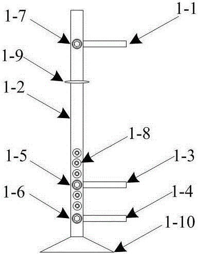
[0025] Oil storage tank water level judging device 1 (see figure 2 ) includes a support rod base 1-10, an adjustable support rod 1-2 is connected to the support rod base 1-10, and the upper part of the adjustable support rod 1-2 is connected to a zero potential contact piece 1- 1. There is a fastening ring 1-9 under the zero-potential contact piece 1-1 on the adjustable support rod 1-2, which is used to fix the adjustable support rod 1-2 on the wall of the storage tank, and the adjustable support rod 1-2 There are several countersunk holes 1-8 for adjusting the water level evenly distributed in the lower part, and the middle and lower part of the adjustable support rod 1-2 is connected to the sewage pump starting ...


PUM


Abstract

The invention discloses an oil-water separating sewage drain device for a transformer oil reservoir. The device is characterized by being composed of an oil reservoir water level determination device (1), an integrated control device (2) and a sewage drain device (3); the oil reservoir water level determination device (1) comprises a supporting rod substrate (1-10), an adjustable supporting rod (1-2), a zero potential contact chip (1-1), a sewage drain pump start contact chip (1-3), and a sewage drain pump stop contact chip (1-4); the integrated control device (2) comprises a control device body (2-13), a power switch (2-6), a liquid crystal display (2-5), and an F21-E1RX remote control device (2-14); the sewage drain device (3) comprises a sewage drain pump (3-1) and a voltage-sensitive relay CJXZ-2510 (3-2). According to the oil-water separating sewage drain device for the transformer oil reservoir, water in the transformer oil reservoir is monitored in real time and drained in time, therefore, the occurrence of an accident that the surrounding environment is damaged due to occurrence of overflow of transformer oil when the oil reservoir is waterlogged is prevented, and the labor intensity of operation and maintenance staff as well as operation and maintenance cost of the device are reduced.

Description

[0001] Technical field: [0002] The invention relates to an oil-water separation and sewage discharge device for a transformer oil storage pool, and belongs to the technical field of power system substation operation and maintenance. [0003] Background technique: [0004] At present, unattended substations of 110kV and above all use oil-immersed transformers for step-up or step-down. Although with the continuous development of power grid technology, the protection of transformers in substations has been very mature, but when accidents such as oil injection and explosion occur in the transformer, the insulating oil in the transformer body will flow to the oil storage pool through the oil receiving pool, and the insulating oil will remain The oil storage tank is no longer discharged outside the station, which plays a role in protecting the surrounding environment. [0005] At present, most transformers are designed outdoors, and the oil receiving pool is at the bottom of the t...

Claims


Application Information

Patent Timeline
Patent Type & Authority Applications(China)
IPC IPC(8): B01D17/025
CPCB01D17/0208
Inventor 李元飞孙建人王英武李现忠于慎航杨涛刘亚栋王亮亮田立伟王天一杨重燕梁欢
Owner YANTAI POWER SUPPLY COMPANY OF STATE GRID SHANDONG ELECTRIC POWER
Why Eureka
Try Eureka