Terminal protecting component of electric compressor

A technology for electric compressors and protection components, which is applied in the direction of machines/engines, pump components, mechanical equipment, etc. It can solve the problems of low installation operability, noise generation, and easy shaking, so as to suppress noise, improve efficiency, and prevent shaking Effect

Inactive Publication Date: 2012-05-30
SANYO ELECTRIC CO LTD
View PDF2 Cites 0 Cited by
  • Summary
  • Abstract
  • Description
  • Claims
  • Application Information

AI Technical Summary

Problems solved by technology

[0008] However, when the terminal cover 2 is inserted and fitted to the above-mentioned terminal guard 1, if Figure 8 As shown in (a), there is a problem that the lower end of the side wall portion 2a of the terminal cover 2 collides with the upper end of the stopper 4 of the terminal guard 1 (including the stoppers 5, 6, the same below), resulting in low installation operability. In addition, as Figure 8 As shown in (b), a gap S1 is generated at the fitting portion of the side wall portion 2a and the stopper 4, etc., and there is a danger of water infiltrating from the gap S1. There are problems such as easy shaking and noise due to the gap S2 between the surfaces

Method used


Image

  • Terminal protecting component of electric compressor
  • Terminal protecting component of electric compressor
  • Terminal protecting component of electric compressor

Examples


Embodiment Construction

[0045] Embodiments of the present invention will be described below with reference to the drawings.

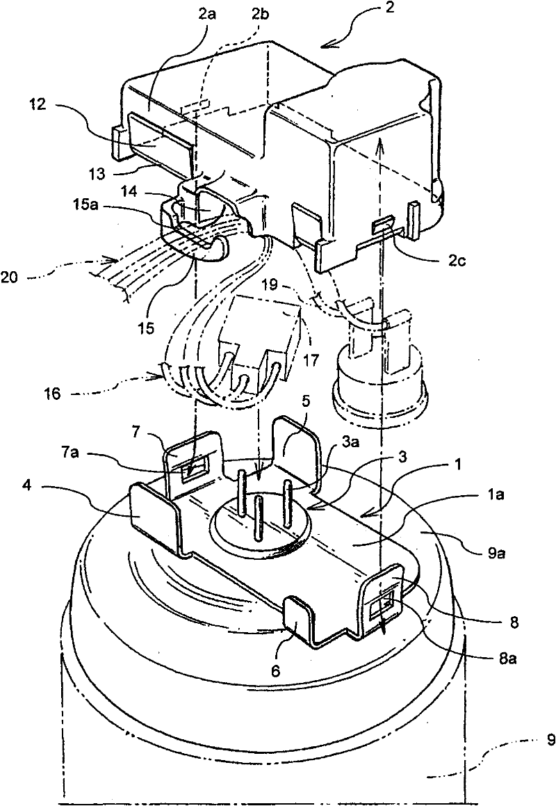
[0046] figure 1 It is a schematic exploded perspective view which shows embodiment of the terminal protection member of the electric compressor concerning this invention. right with Figure 6 In the conventional example shown, substantially the same members are denoted by the same reference numerals as those described above.

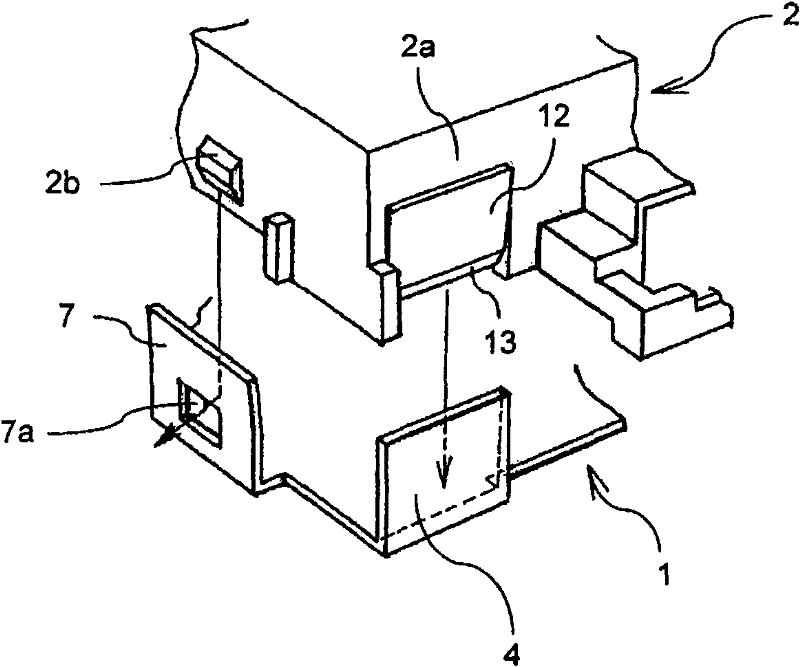
[0047] exist figure 1 Among them, 1 is a terminal guard made of steel plate, which penetrates the terminal 3 fixed to the top of the lid body 9a of the airtight container 9 and is attached to the lid body 9a. The side portion of the base plate 1a of the terminal guard 1 is vertically provided with blocking pieces 4, 5, and the side portion on the same side as the blocking piece 4 is vertically provided with a small blocking piece 6, and is vertically opposed at the end. Locking pieces 7, 8 are provided, and these locking pieces 7, 8 are formed with ...


PUM


Abstract

The present terminal protecting component of an electric compressor improves mounting operations of a terminal cover without clearance of a jogged blocking portion relative to a terminal protecting piece. The protecting component is composed of the terminal protecting piece penetrated and fixed on a terminal mounted in a closed container of the electric compressor and mounted on a lid body and the terminal cover (2) jogged and fixed on the terminal protecting piece. The inner sides of a plurality of blocking sheets (4) formed on one side of the terminal protecting piece vertically is jogged and fixed with a side wall portion (2a) of the terminal cover (2), and protuberances (2b, 2c) are jogged in blocking holes (7a, 8a) of blocking sheets (7, 8) formed on one side of the terminal protecting piece vertically respectively. An outer side of the side wall portion (2a) is provided with a projecting portion (12), and a lower end portion is provided with an inclined plane (13) sloping inward. When the side wall portion (2a) is jogged on the blocking sheets of the terminal protecting piece, there is non clearance between the side wall portion and the blocking sheets (4), and the lower endof the side wall portion conjoins to an upper surface of a substrate of the terminal protecting piece.

Description

technical field [0001] The present invention relates to an electric compressor, and particularly relates to an improvement of a protection member for protecting a terminal attached to an airtight container. Background technique [0002] Generally, an electric compressor houses a motor mechanism unit and a compression mechanism unit driven by the motor mechanism unit in an airtight container, and a terminal is installed in the airtight container. action. Then, gas (generally, coolant) is introduced into the compression mechanism through the introduction pipe and compressed, and at the same time, the high-pressure gas ejected from the airtight container is discharged to the outside through the discharge pipe. [0003] The external electrode of the terminal located outside the airtight container is connected to the flexible wire terminal of the power supply, so the electrical connection part is exposed to the outside. Therefore, if the electrical connection part is exposed to...

Claims


Application Information

Patent Timeline
Patent Type & Authority Patents(China)
IPC IPC(8): F04B39/00
Inventor 小林正英
Owner SANYO ELECTRIC CO LTD
Why Eureka
Try Eureka