Light guide bar with patterned surface to enhance light uniformity and intensity

A patterned surface, light uniformity technology, applied in the direction of light guide, optical fiber light guide, light guide of lighting system, etc., can solve the problems of increased light source cost, non-uniform luminosity, dim light, etc. effect of life

Inactive Publication Date: 2010-01-06
PIXON TECH CORP
View PDF5 Cites 11 Cited by
  • Summary
  • Abstract
  • Description
  • Claims
  • Application Information

AI Technical Summary

Problems solved by technology

But this will lead to an increase in the cost of the aforementioned light source
[0005] In addition, since only one light emitting diode 110 is used as the light source in the traditional light source, this will cause the light generated near the light emitting diode 110 to be relatively bright; , the resulting light is dimmer
As a result, the luminosity produced by this traditionally produced light source is not uniform

Method used


Image

  • Light guide bar with patterned surface to enhance light uniformity and intensity
  • Light guide bar with patterned surface to enhance light uniformity and intensity
  • Light guide bar with patterned surface to enhance light uniformity and intensity

Examples


Embodiment Construction

[0039] Preferred embodiments of the present invention are described in detail below, and accompanying drawings are used to illustrate examples thereof. And wherever possible, the same reference numbers are used in the drawings and descriptions to refer to the same or similar components.

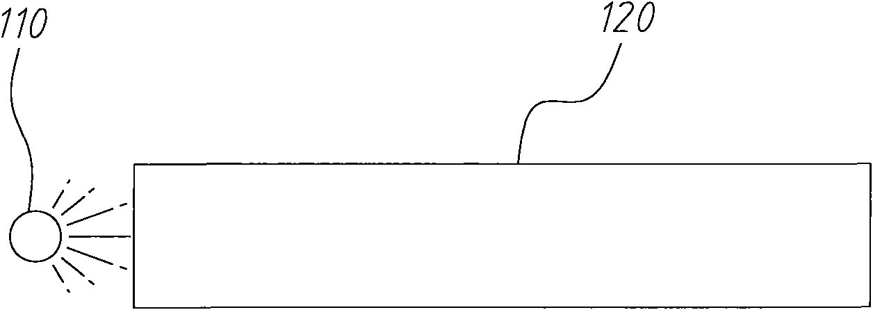
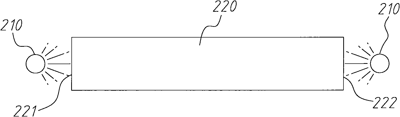
[0040] Figure 2A It is a schematic diagram of an embodiment of a flicker-free light source with a light guide column described in the present invention. The flicker-free light source includes an LED light source 210 placed at each end of the light guide bar 220 . The light guide column 220 is made of a transparent or semi-transparent, semi-hollow, hollow or solid cubic material. The light guiding column 220 further includes two ends 221 , 222 .

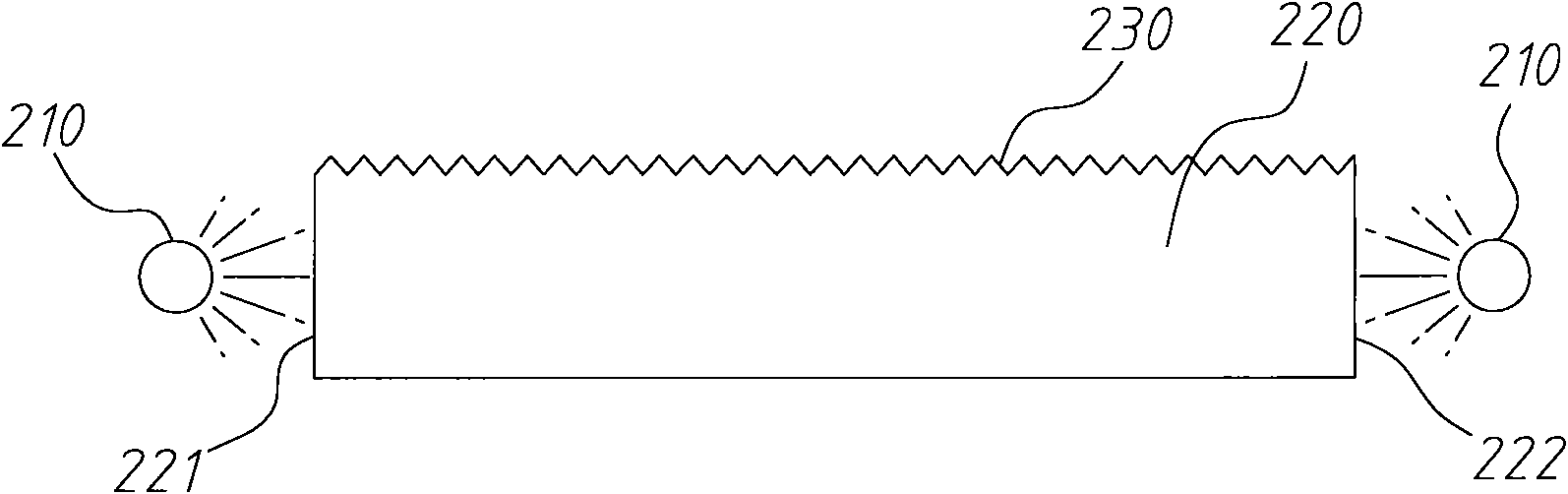
[0041] Figure 2B It is a schematic diagram of an embodiment of a light guide column for a flicker-free light source with a light diffusion patterned surface according to the present invention.

[0042] Figure 2B As shown, in addition to the ...


PUM


Abstract

The present invention discloses a light guide bar with a patterned surface for a flicker free light source comprising a light emitting diode (LED) light source disposed on each end of the light guide bar. A light diffusing pattern is disposed on a light emitting surface. The light diffusing pattern comprises a plurality of notches that are smallest closest to the LED light sources and largest in the center of the light guide bar. A light reflecting pattern is disposed on a light reflecting surface opposite the light diffusing pattern on the light emitting surface. Light emitted by the LED light sources enters the light guide bar through the ends. The light travels through the light guide bar at various angles and is reflected by the light reflecting pattern on the light reflecting surface. The reflected light is then emitted through the light diffusing pattern on the light emitting surface.

Description

technical field [0001] The invention relates to a patent related to a light source, in particular to a light source device with high efficiency and no flicker, which can provide a uniform emission of light. Background technique [0002] Linear lights emit light in different directions from the original light source. For example, a light-emitting diode emits light at an angle of zero degrees. By influencing the direction of the beam, the linear light source can also emit light at different angles, eg 90 degrees. [0003] refer to figure 1 , which is a light source diagram described in the prior art. Such as figure 1 As shown, the conventional light source includes a light emitting diode 110 and a transparent light rod 120 . Both ends of the transparent light rod 120 are flat surfaces. When the LED 110 is powered on, the LED 110 generates light. Part of the light enters the transparent light rod 120 . Since both ends of the transparent light rod 120 are flat surfaces, ...

Claims


Application Information

Patent Timeline
Patent Type & Authority Applications(China)
IPC IPC(8): F21V8/00F21Y101/02
CPCG02B6/0038G02B6/001
Inventor 吴荣曜颜志明廖建良陈彦杰
Owner PIXON TECH CORP
Why Eureka
Try Eureka