Spare power automatic switching method and device

A technology of self-switching and switching, which is applied in the field of electric power, can solve inaccurate problems, achieve the effects of reducing economic losses, increasing speed, and reducing power outage time

Inactive Publication Date: 2015-06-03
STATE GRID CORP OF CHINA +2
View PDF7 Cites 9 Cited by
  • Summary
  • Abstract
  • Description
  • Claims
  • Application Information

AI Technical Summary

Problems solved by technology

[0010] The main purpose of this application is to provide a method and device for self-initiation of backup, to at least solve the problem of inaccuracy caused by using a comparator to realize the solution for automatic transfer of backup

Method used


Image

  • Spare power automatic switching method and device
  • Spare power automatic switching method and device
  • Spare power automatic switching method and device

Examples


Embodiment 1

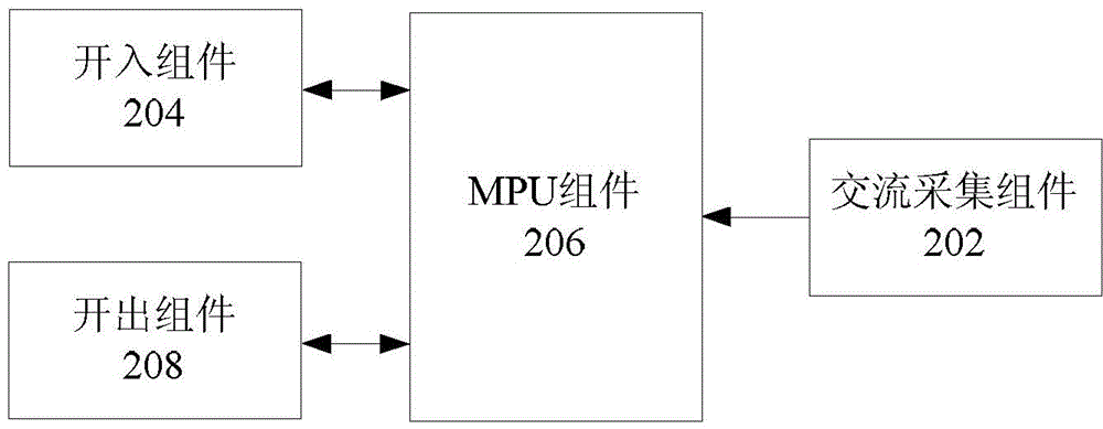
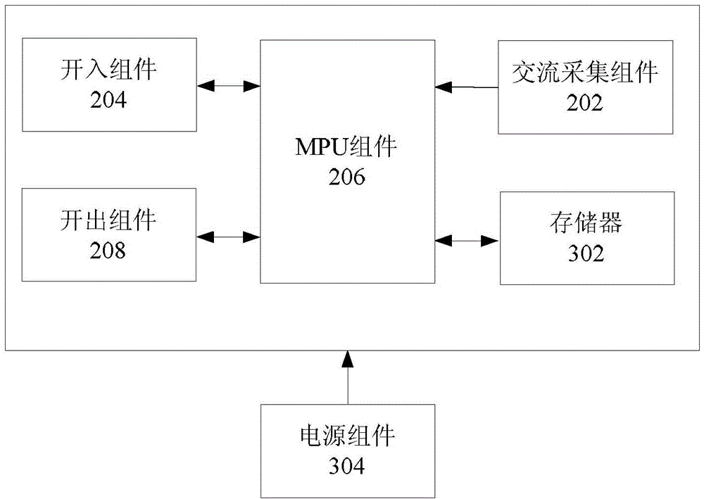
[0037] figure 2 It is a schematic structural view of the self-injection device according to the embodiment of the present application, such as figure 2 As shown, the self-injection device of this embodiment includes but is not limited to:

[0038] 1) The AC acquisition component 202 is connected to the microprocessor component 206 (MPU component 206), and is used to convert the collected current signal and voltage signal of the field switch in proportion to obtain a microprocessor (MPU, Micro Processor Unit) a current input signal and a voltage input signal identified by component 206;

[0039] As an optional embodiment, the current signal of the on-site switch is transformed by the current transformer and connected to the AC acquisition component of the device at the same time as the voltage signal, and the AC acquisition component converts the voltage and current signal into a small signal in proportion and then inputs it to the MPU component The analog-to-digital conver...

Embodiment 2

[0062] exist Figure 1-Figure 4 On the basis of the shown standby automatic switch-on device, this embodiment also provides a standby automatic switch-on method, such as Figure 5 As shown, the self-injection method in the present embodiment includes the following steps:

[0063] S502, acquiring the current input signal and the voltage input signal that can be recognized by the microprocessor (MPU, Micro Processor Unit) component obtained by converting the collected current signal and voltage signal of the on-site switch in proportion;

[0064] S504, acquiring the switch operating parameters converted from the collected operating parameters of the on-site switches and recognizable by the microprocessor component;

[0065] S506, generating switch control information according to the current input signal, voltage input signal and switch operation parameters;

[0066] S508. Control the change of the on-off state of the field switch according to the switch control information, w...


PUM


Abstract

The invention discloses a spare power automatic switching method and device, wherein the method comprises the following steps that current input signals and voltage input signals which are obtained through proportionally converting collected current signals and voltage signals of an on-site switch and can be recognized by a microprocessor assembly are obtained; switch operation parameters which are obtained through converting collected operation parameters of the in-site switch and can be recognized by the microprocessor assembly are obtained; switch control information is generated according to the current input signals, the voltage input signals and the switch operation parameters; the on-off state change of the in-site switch is controlled according to the switch control information, wherein the on-off state change of the in-site switch is used for switching a spare power supply to the work state when a main power consumption power supply fails, and is also used for switching the main power consumption power supply to the work state when the main power consumption power supply recovers the normal state. The method and the device have the advantages that the problem of spare power automatic switching inaccuracy is solved, and the effect of accurate, flickering-free and fast spare power automatic switching is realized, and the realized functions are complete.

Description

technical field [0001] The present application relates to the field of electric power, in particular, to a method and device for self-starting equipment. Background technique [0002] In recent years, with the rapid development of distribution networks and the introduction of smart grids, the requirements for power supply reliability are getting higher and higher, especially for important users. Generally, dual power supplies are used, and the two power supplies are controlled by dual power supplies. implement mutual backup; [0003] At present, basically all important power distribution rooms have installed low-voltage programmable control backup automatic switching devices (PLC devices), and the automatic switching function of the backup power supply and the loop selection and adjustment function are completed through the PLC device, but due to the limitations of the PLC itself , in the case of the continuous improvement of power supply reliability requirements and the ra...

Claims


Application Information

Patent Timeline
Patent Type & Authority Applications(China)
IPC IPC(8): H02J9/06
Inventor 李洪涛陈奎阳汤定阳赵奕刘晓娟
Owner STATE GRID CORP OF CHINA
Why Eureka
Try Eureka