Optical plate and backlight module adopting same

An optical plate and light source technology, applied in optics, optical components, nonlinear optics, etc., can solve problems such as light loss, reduce light utilization rate, increase light transmission interface loss, etc.

Inactive Publication Date: 2010-01-06
HONG FU JIN PRECISION IND (SHENZHEN) CO LTD +1
View PDF0 Cites 2 Cited by
  • Summary
  • Abstract
  • Description
  • Claims
  • Application Information

AI Technical Summary

Problems solved by technology

However, when the light is transmitted in the upper diffusion sheet 14, part of the light will be absorbed by the upper diffusion sheet 14 and cause part of the light loss; and the use of the upper diffusion sheet 14 will also increase the number

Method used


Image

  • Optical plate and backlight module adopting same
  • Optical plate and backlight module adopting same
  • Optical plate and backlight module adopting same

Examples


Embodiment Construction

[0017] The optical plate of the present invention will be further described in detail below with reference to the drawings and embodiments.

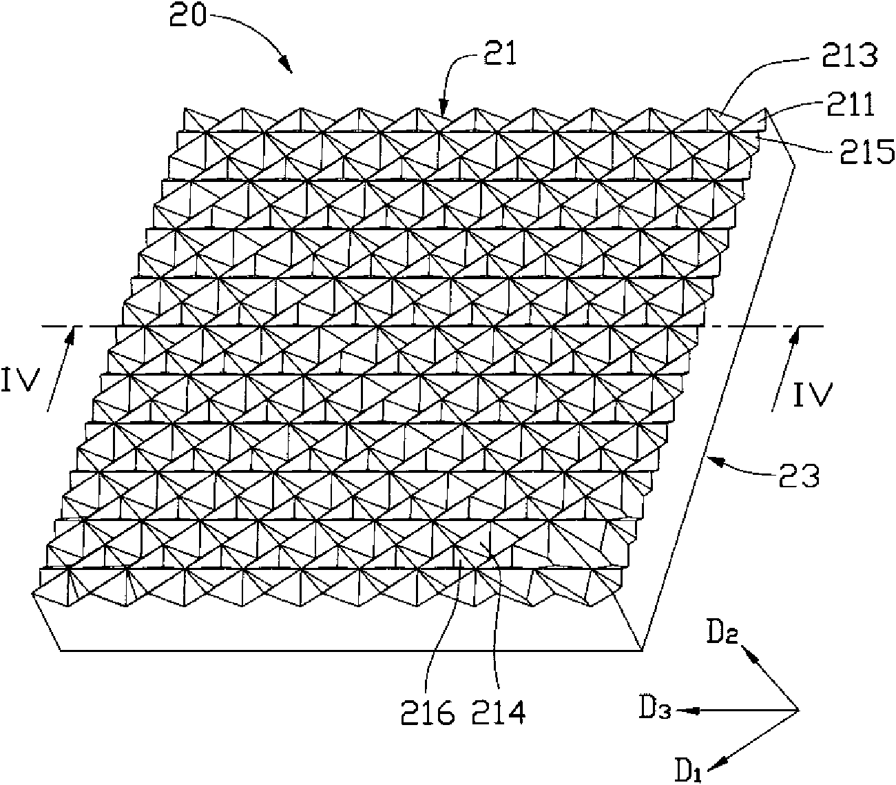
[0018] See image 3 and Figure 4 , shows the optical plate 20 of the preferred embodiment 1 of the present invention, which is composed of a transparent body, and the transparent body includes a light-emitting surface 21 and a bottom surface 23 opposite to the light-emitting surface 21 . The light emitting surface 21 has a plurality of 1 Extended first V-shaped protrusions 211, a plurality of extending along the second direction D 2 The extended second V-shaped protrusion 213 and a plurality of 3 The extended third V-shaped protrusion 215, the first V-shaped protrusion 211 intersects with the second V-shaped protrusion 213 to form a plurality of intersection points, and the third V-shaped protrusion 215 passes through some of the intersection points. The bottom surface 23 is a smooth surface, and it can be understood that the bottom...


PUM

PropertyMeasurementUnit
Top angleaaaaaaaaaa

Abstract

An optical plate comprises a transparent body which comprises a light extraction surface and a bottom surface opposite to the light extraction surface; wherein, a plurality of triangular pyramid shaped grooves and a plurality of rectangular pyramid shaped grooves are formed on the light extraction surface; each rectangular pyramid shaped groove is enclosed by four triangular pyramid shaped grooves. The invention also provides a backlight module adopting the optical plate. The backlight module has the advantages of improving efficient utilization ratio of light and enjoying uniformity of light emission.

Description

technical field [0001] The invention relates to an optical plate and a backlight module using the optical plate. Background technique [0002] See figure 1 and figure 2 , shows an existing direct-lit backlight module 100, which includes a frame 11, a plurality of light sources 12 arranged inside the frame 11, a diffusion plate 13 arranged above the light sources 12 and covering the frame 11, and A prism sheet 10. Wherein, the diffusion plate 13 generally contains scattering particles for diffusing light. The prism sheet 10 includes a transparent substrate 101 and a prism layer 103 formed on the transparent substrate 101 . The prism layer 103 has a plurality of elongated V-shaped protrusions 105 . [0003] During use, the light generated by the plurality of light sources 12 enters the diffuser plate 13 and is uniformly diffused, then continues to enter the prism sheet 10, and under the action of the elongated V-shaped protrusions 105 of the prism sheet 10, the outgoing ...

Claims


Application Information

Patent Timeline
IPC IPC(8): G02B6/00G02B1/04G02F1/13357
CPCG02B5/045G02B5/02G02B6/0053
Inventor 章绍汉
Owner HONG FU JIN PRECISION IND (SHENZHEN) CO LTD
Why Eureka
Try Eureka