
Combined counterweight device and crane using same
A technology of counterweight and additional counterweight, applied in cranes and other directions, can solve the problem of long length of the whole machine, and achieve the effects of compact layout, improved driving performance, and reduced length
- Summary
- Abstract
- Description
- Claims
- Application Information
AI Technical Summary
Problems solved by technology
Method used
Image

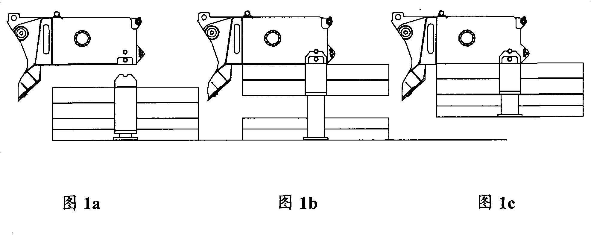
Examples
Embodiment Construction
[0030] The present embodiment will be described in detail below in conjunction with the accompanying drawings.
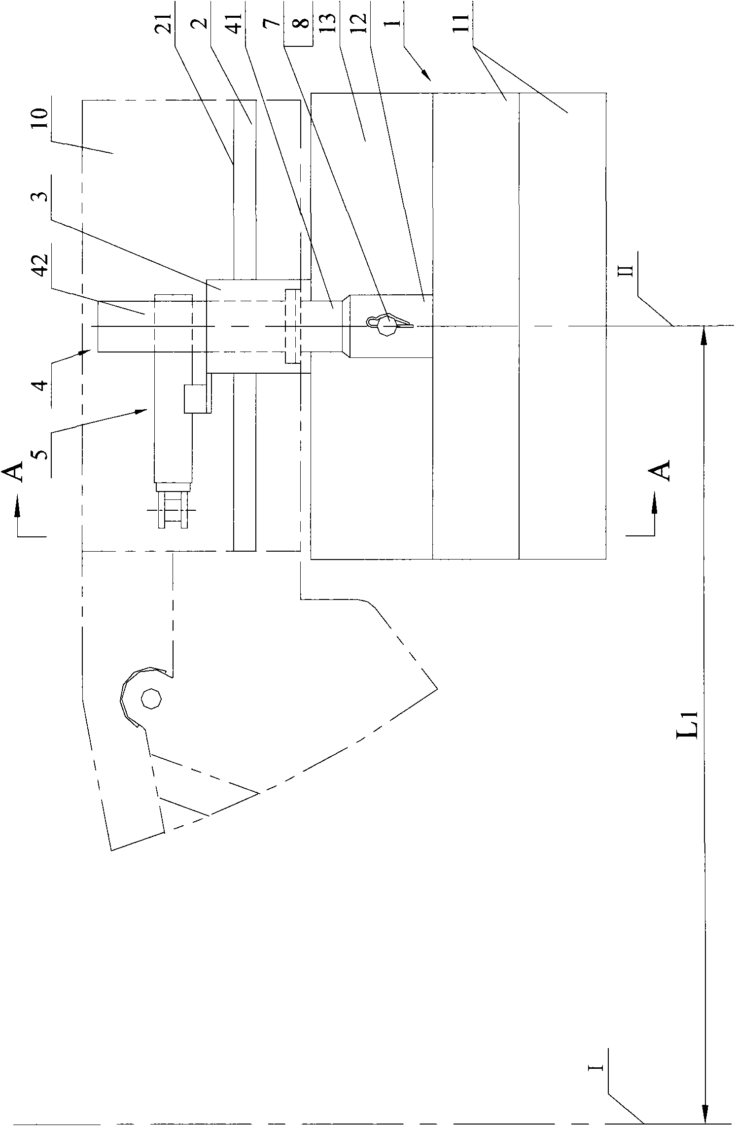
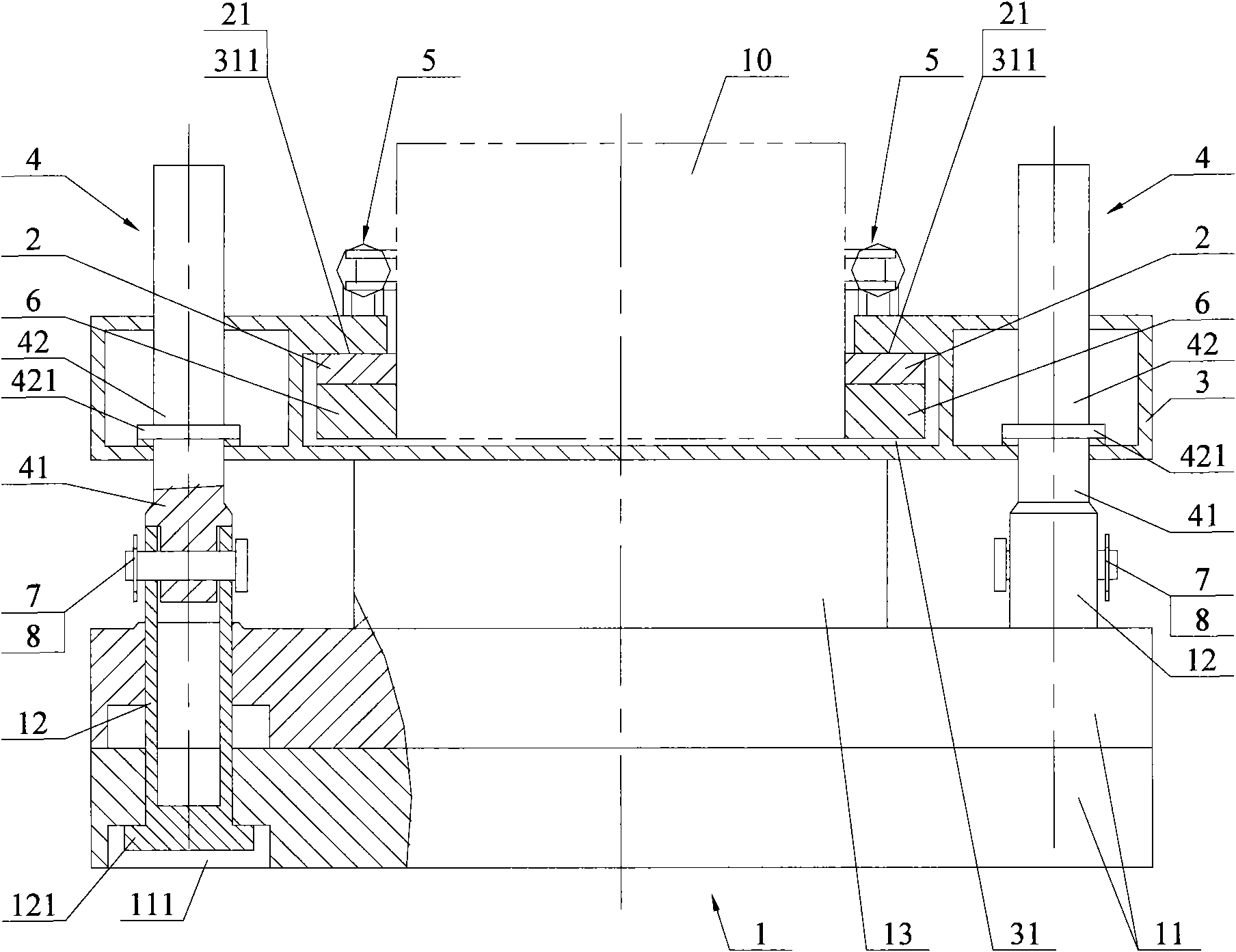
[0031] See Figure 2a and Figure 2b ,in, Figure 2a It is a schematic diagram of the lateral structure of the combined balance weight device of the present invention, Figure 2b Yes Figure 2a A-A cutaway view.
[0032] As shown in the figure, this embodiment mainly includes a counterweight body 1, two horizontal slide rails 2, a counterweight bracket 3, two vertical oil cylinders 4 and two horizontal oil cylinders 5; Below the tail 10.
[0033] Wherein, the two horizontal slide rails 2 are respectively fixedly arranged on the left and right side walls of the car body turntable tail 10, as Figure 2bAs shown, on the left and right side walls of the rear part 10 of the car body turntable under the two horizontal slide rails 2, slide rail brackets 6 for carrying are fixedly arranged respectively. In particular, the front, rear, left and right directions involv...
PUM
 Abstract
Description
Claims
Application Information