High-temperature and high-pressure positive action desuperheater

A high-temperature, high-pressure, positive-acting technology, applied in superheating temperature control, steam superheating, steam generation, etc., can solve the problems of metal piston ring wear, vibration, and high cost of replacing spare parts, so as to improve the up and down orientation, improve the service life, The effect of low maintenance cost

Active Publication Date: 2011-04-06
无锡卓尔阀业有限公司
View PDF0 Cites 0 Cited by
  • Summary
  • Abstract
  • Description
  • Claims
  • Application Information

AI Technical Summary

Problems solved by technology

However, there is a common problem that is difficult to solve in this type of desuperheater, that is, the sealing of the metal piston ring used on the plunger valve core used to adjust the opening quantity of the nozzle.
The metal piston ring is easy to wear during work, which will cause the gap between the piston ring and the inner hole of the nozzle sleeve to increase until the inner hole of the sleeve is damaged
This will affect the flow into each nozzle, thereby affecting the regulated flow of desuperheating water
With the increase of wear and tear, it will fail, and finally the flow of desuperheating water cannot be controlled
This type of desuperheater generally wears out after half a year to two years, affecting normal use
And because the nozzle sleeve and spool wear out at the same time, the cost of replacing spare parts is very high
caused great trouble to users
In addition, due to the increased gap after the wear of the piston ring and the nozzle sleeve, the desuperheater cannot be guided when it is working, and oscillation will occur

Method used


Image

  • High-temperature and high-pressure positive action desuperheater
  • High-temperature and high-pressure positive action desuperheater
  • High-temperature and high-pressure positive action desuperheater

Examples


Embodiment Construction

[0013] The specific embodiments of the present invention will be further described below with reference to the accompanying drawings.

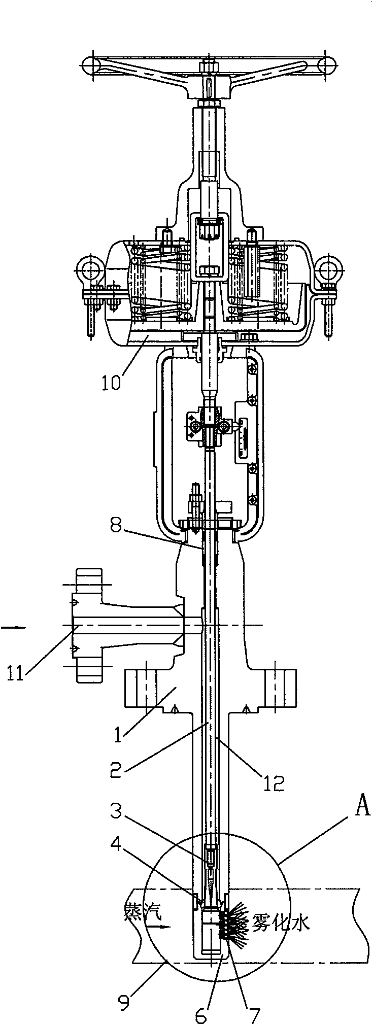
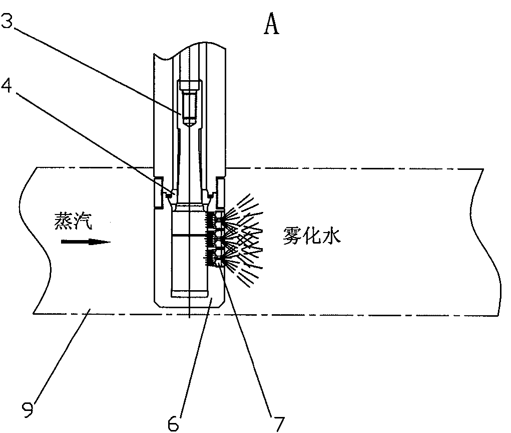
[0014] like Figure 1 to Figure 4 As shown, the present invention includes a valve body 1, a desuperheating water inlet 11 provided on the valve body 1 is communicated with a valve cavity 12 in the valve body 1, a valve stem 2 is arranged in the valve cavity 12, and the lower end of the valve stem 2 is fixed with a A nozzle sleeve 6 is fixed on the lower end of the valve core 3 and the valve body 1 , and a vortex atomizing nozzle 7 is arranged on the side wall of the nozzle sleeve 6 .

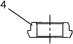
[0015] A valve seat 4 is arranged between the valve body 1 and the nozzle sleeve 6, and the valve core 3 cooperates with the valve seat 4 to adjust the flow rate of the desuperheating water, which can be tightly closed. Because the valve core 3 and valve seat 4 are in the form of single-seat sealing, the leakage level of the desuperheater can be increased from...


PUM


Abstract

The invention relates to a high-temperature and high-pressure positive action desuperheater, comprising a valve body. A attemperation water inlet arranged on the valve body is communicated with a valve cavity arranged in the valve body, a valve rod is arranged in the valve cavity, a valve core is fixed at the lower end of the valve rod, a nozzle sleeve is fixed at the lower end of the valve body,a nozzle is arranged on the side wall of the nozzle sleeve, a valve seat is arranged between the valve body and the nozzle sleeve, the valve core is matched with the valve seat, and at least one groove the depth of which is gradually decreased along the axial direction is arranged on the side wall of the valve core. In the invention, a metal piston sealing ring is cancelled so that the abrasion of the inner wall of the nozzle sleeve can not be caused, and the service life of the desuperheater is greatly prolonged with favorable sealing performance; in addition, the groove with the depth gradually decreased is designed on the valve core and is synchronously regulated with the nozzle of the nozzle sleeve, thereby playing a role of linear or equal percent accurate flow regulation.

Description

technical field [0001] The invention relates to a high-temperature and high-pressure positive-action desuperheater, which is mainly used for precise temperature reduction control of superheated steam in boilers and steam turbine systems of power plants, petrochemicals, metallurgy, papermaking, etc. Background technique [0002] There are two main types of desuperheaters used for superheated steam desuperheating control: [0003] The first is a split desuperheater, which is composed of a desuperheating water regulating valve and a fixed nozzle. The flow of desuperheating water is controlled by the desuperheating water regulating valve during operation, and the nozzle sprays the desuperheating water into the steam pipeline to achieve the purpose of lowering the steam temperature to the set value. In the desuperheater of this structure, no matter the amount of desuperheating water, the nozzle is always open, so the atomization effect will be poor, especially when the flow rate...

Claims


Application Information

Patent Timeline
Patent Type & Authority Patents(China)
IPC IPC(8): F22G5/12
Inventor 吴杰
Owner 无锡卓尔阀业有限公司
Why Eureka
Try Eureka