Camera detecting equipment and system

A technology of detection equipment and camera, applied in photography, instrumentation, optics, etc., can solve the problems of inaccurate detection and calculation of image deviation value, etc., and achieve the effect of strong practicability and simple operation

Active Publication Date: 2012-01-25
BYD SEMICON CO LTD
View PDF6 Cites 0 Cited by
  • Summary
  • Abstract
  • Description
  • Claims
  • Application Information

AI Technical Summary

Problems solved by technology

However, the conventional camera function test cannot accurately detect this, let alone calculate the specific deviation value of the image.

Method used


Image

  • Camera detecting equipment and system
  • Camera detecting equipment and system
  • Camera detecting equipment and system

Examples


Embodiment Construction

[0014] Specific embodiments of the present invention will now be described in detail, examples of which are illustrated in the accompanying drawings, wherein identical or similar reference numerals designate identical or similar elements. The present invention is described below by referring to the accompanying drawings, which are only for explaining the present invention, but not construed as limiting the present invention.

[0015] In addition, it should be noted that in the description of the present invention, the terms "first, second, X-axis, Y-axis, Z-axis" and other descriptions are only for the convenience of the description of the present invention, and cannot be interpreted as the definition of the present invention. limit.

[0016] In addition, it should be noted that the term "top board" is relative to the bottom board, and is a board to be connected to the upper surface and / or lower surface of the bottom board, and may also be called a "sub-board", etc. It is for...


PUM


Abstract

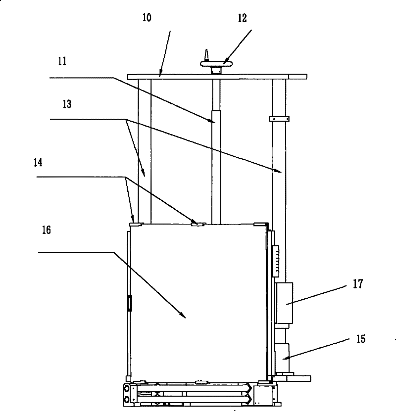
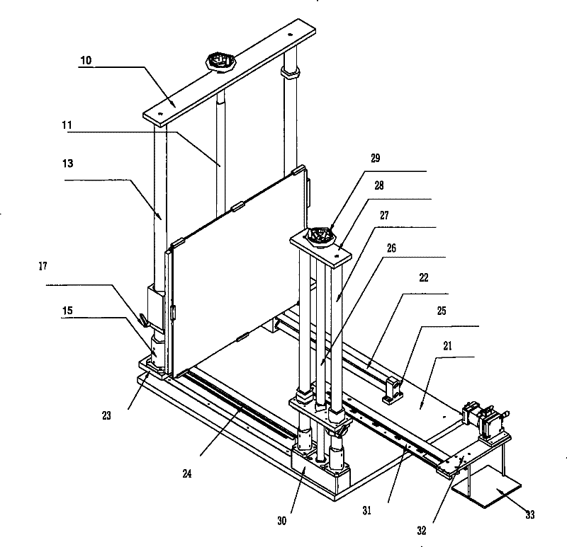
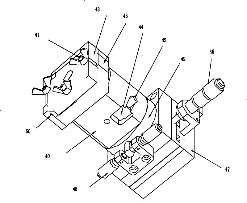
The invention discloses camera detecting equipment, which comprises a base, a support, a test graph fixing frame and a camera fixing bracket, wherein the support is arranged on the base and can move on the base along the Y-axis direction; the test graph fixing frame is used for fixing a test graph, arranged on the support and can move on the support in the Z-axis direction; the camera fixing bracket is arranged on the base; and a camera to be detected is arranged on the camera fixing bracket, so that the camera is opposite to the test graph arranged on the test graph fixing frame. The invention also discloses a camera detecting system. The equipment provided by the invention can be fixed on a worktable, and related test parts can be adjusted along a screw rod and are stable so as to assist a computer to detect and calculate the central offset and rotation angle of an image shot by the camera and meet the higher level requirement on the quality of the shot image.

Description

technical field [0001] The present invention relates to the field of image quality detection, in particular, the present invention relates to a camera detection device and system. Background technique [0002] During the assembly process of the camera, it is easy for the center of the photosensitive area of ​​the camera chip and the optical center of the lens (Lens) to not be on the same straight line, resulting in center shift and image rotation when the camera captures images, which affects the imaging effect. Therefore, before the camera leaves the factory, the performance of the camera must be tested to ensure that the center shift and image rotation of the camera when capturing images meet the relevant parameter requirements. The conventional camera function test cannot accurately detect this, let alone calculate the specific deviation value of the image. Contents of the invention [0003] The object of the present invention is to provide a camera detection device an...

Claims


Application Information

Patent Timeline
Patent Type & Authority Patents(China)
IPC IPC(8): G03B43/00
Inventor 李水华霍娜唐建伟
Owner BYD SEMICON CO LTD
Why Eureka
Try Eureka