The connection structure of the thin film electrode and the shell

A technology of thin film electrode and connection structure, applied in the field of connection structure between thin film electrode and shell, can solve the problems of increasing the size of thin film electrode and external structure, and achieve the effect of not easy to loosen, avoid size limitation, and reliable connection

Active Publication Date: 2021-01-26
HANGZHOU WEIMING XINKE TECH CO LTD +1
View PDF3 Cites 0 Cited by
  • Summary
  • Abstract
  • Description
  • Claims
  • Application Information

AI Technical Summary

Problems solved by technology

[0003] The object of the present invention is to at least solve the problem of size increase during the connection of thin film electrodes to external structures

Method used


Image

  • The connection structure of the thin film electrode and the shell
  • The connection structure of the thin film electrode and the shell
  • The connection structure of the thin film electrode and the shell

Examples


Embodiment approach 1

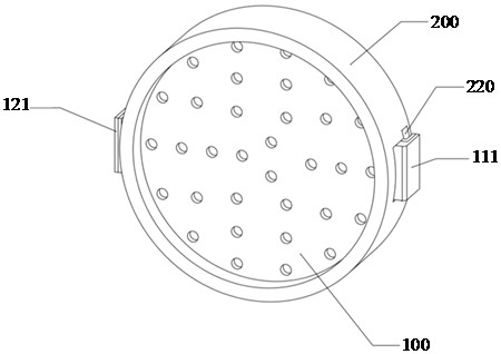
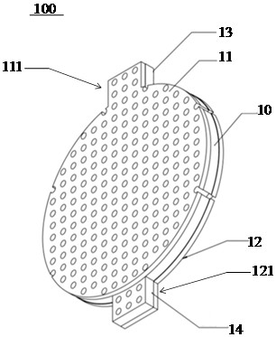
[0039] to combine Figure 1 to Figure 5 As shown, the connection structure between the thin film electrode and the case of this embodiment includes a thin film electrode unit 100 and a case 200 . The membrane electrode unit 100 includes a porous membrane 10 , a first electrode 11 and a second electrode 12 , and the first electrode 11 and the second electrode 12 are attached to two sides of the porous membrane 10 . Wherein, the porous film 10 of this embodiment is a flexible porous film, the first electrode 11 only covers the central circular part of the porous film 10 and the first protruding end 13 , and the second protruding end 14 is not covered by the first electrode 11 . The second electrode 12 only covers the central circular part and the second extension 14 of the porous film 10, and the first extension 13 has no second electrode 12 to cover, so that the first extension 13 and the first extension 13 covering its surface The electrode 11 forms a first electrical connect...

Embodiment approach 2

[0052] to combine Figure 6 to Figure 9 As shown, the porous film 10 of this embodiment is a rigid porous film, and the porous film 10 has a circular structure without the setting of the protruding end. The first electrode 11 is modified on one side of the porous film 10 by sputtering, atomic layer deposition, chemical vapor deposition, electroless deposition, etc., and during the modification process, the same side is covered by a mask for forming the second electrode. A portion of linker unit 121 forms an optional modification. In the same way, the second electrode 12 is selectively modified on the other side of the porous film 10, and during the modification process, the part used to form the first electrical connection unit 111 on the same side is covered by a mask, wherein the first The first electrical connection unit 111 and the second electrical connection unit 121 are arranged at a certain angle to avoid a short circuit during the electrical connection with the casin...

Embodiment approach 3

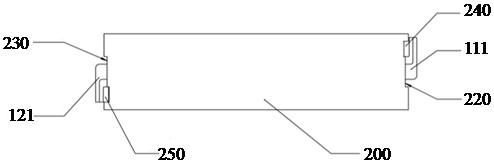
[0059] to combine Figure 10 with Figure 11As shown, the porous film 10 of this embodiment is also a rigid porous film. The inner wall surface on the casing 200 is also provided with a first sample adding groove 270 and a second sample adding groove 280, and the first sample adding groove 270 and the second sample adding groove 280 are respectively arranged on both sides of the installation groove 210, and are respectively connected with The first electrical connection unit 111 and the second electrical connection unit 121 are disposed opposite to each other, a first exhaust hole 271 is provided on the first sample adding tank 270 , and a second exhaust hole is provided on the second sample adding tank 280 . Wherein, the exhaust hole and the sample adding groove can be made on the casing 200 by machining, injection molding, etching, 3D printing and other methods. In this embodiment, the casing 200 also includes a first casing and a second casing connected in a detachable ma...


PUM


Abstract

The invention belongs to the technical field of electrode equipment, and in particular relates to a connection structure between a thin film electrode and a casing. The electrical connection structure of the present invention includes at least one film electrode unit and a housing, the film electrode unit includes a porous film, a first electrode and a second electrode, the first electrode and the second electrode are attached to both sides of the porous film, and the part is porous The film and part of the first electrodes form a first electrical connection unit, and part of the porous film and part of the second electrodes form a second electrical connection unit. The inner wall of the casing is provided with at least one installation groove, and the film electrode unit is arranged in the installation groove. The outer wall of the body is also provided with at least one communication unit communicating with the installation groove, and the first electrical connection unit and the second electrical connection unit are respectively communicated with the external circuit of the casing through the communication unit. According to the connection structure of the present application, the effective electrical connection between the thin film electrode and the external circuit of the casing can be realized, and looseness is not easy to occur, thereby ensuring a firm connection between the thin film electrode and the casing.

Description

technical field [0001] The invention belongs to the technical field of electrode equipment, and in particular relates to a connection structure between a thin film electrode and a casing. Background technique [0002] In medical devices, especially for implantable medical devices, because the safety of medical devices and the stability of long-term implantation need to be considered, the electrical connection method of electrodes must have good reliability and mechanical stability. In addition, due to the high degree of integration and miniaturization of implantable medical devices, the size of the electrodes thereof is small, and the requirements for the degree of integration of multiple electrodes are high. Among them, the thickness of the thin-film composite electrode is at the micron level, and wire bonding is mostly used for electrical connection with the external structure. However, considering that the thin film composite electrode is thin and the wire used is thin a...

Claims


Application Information

Patent Timeline
Patent Type & Authority Patents(China)
IPC IPC(8): H05K7/00H05K5/02
CPCH05K7/005H05K5/0247H01B5/14
Inventor 杨倩李良高猛叶乐
Owner HANGZHOU WEIMING XINKE TECH CO LTD
Why Eureka
Try Eureka