Secondary transmission pressing structure

A two-stage transmission and pressing core technology, which is applied in the field of forging machinery, can solve the problems of increasing the overall size of the pressing core, increasing the overall size of the mold, and increasing the cost of mold development.

Active Publication Date: 2014-09-03
ANHUI JIANGHUAI AUTOMOBILE GRP CORP LTD
View PDF7 Cites 0 Cited by
  • Summary
  • Abstract
  • Description
  • Claims
  • Application Information

AI Technical Summary

Problems solved by technology

[0004] The existing punching machine has the following disadvantages: after the space at the bottom of the pressing core of the frame structure is increased, the overall size of the pressing core is increased, and the overall size of the mold is also increased accordingly, which increases the cost of mold development; furthermore, due to the The increased size requires a larger working surface of the stamping machine tool, which also increases the cost of stamping production to a certain extent

Method used


Image

  • Secondary transmission pressing structure
  • Secondary transmission pressing structure
  • Secondary transmission pressing structure

Examples


Embodiment Construction

[0024] Specific embodiments of the present invention will be described in detail below in conjunction with the accompanying drawings.

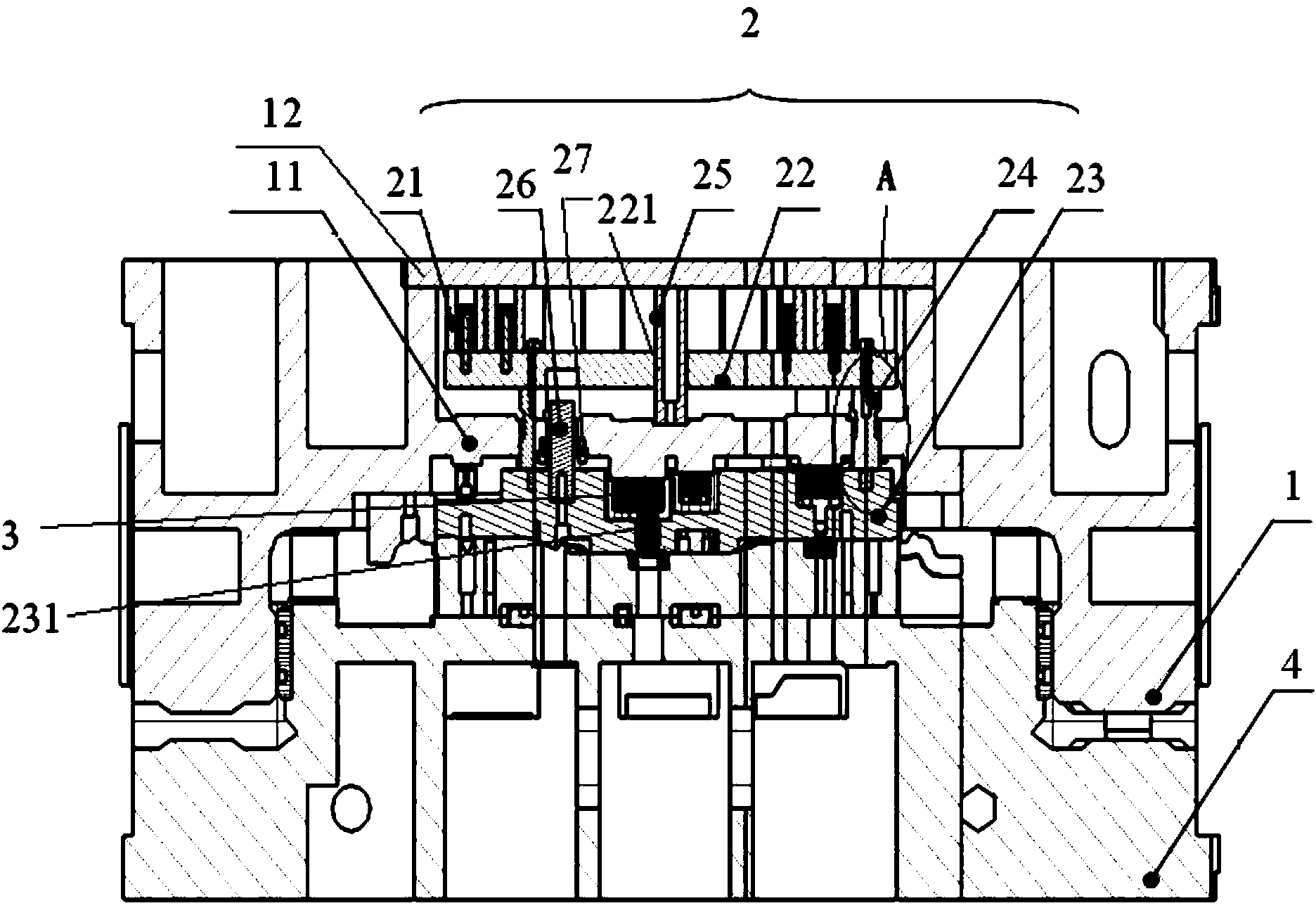
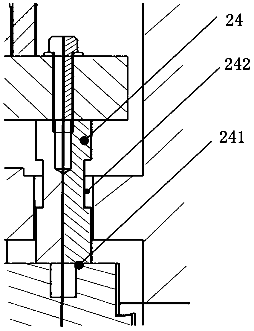
[0025] Such as figure 2 As shown, the two-stage transmission pressing structure 2, the cutter 3 of the punching machine is installed on the upper die horizontal plate 11 of the upper die base 1, and the two-stage transmission pressing material structure 2 includes an elastic element 21 fixed with the upper die base 1, and The secondary transmission backing plate 22 connected to the elastic element 21, the binder core body 23 fixedly connected with the secondary transmission backing plate 22, the secondary transmission backing plate 22 and the binder core body 23 are respectively located on both sides of the upper mold horizontal plate 11 , The binder core body 23 has a through hole 231 for the tool 3 to pass through. Tool 3 can be tools such as a punch, a flanging tool, a shaping tool, a trimming tool, image 3 The tool shown is a trimming ...


PUM


Abstract

The invention provides a secondary transmission pressing structure. A cutter of a punch is installed on an upper die transverse plate of an upper die base. The secondary transmission pressing structure comprises an elastic element, a secondary transmission base plate and a pressing core body, wherein the elastic element is fixedly connected with the upper die base, the secondary transmission base plate is connected with the elastic element, the pressing core body is fixedly connected with the secondary transmission base plate, the secondary transmission base plate and the pressing core body are located on the two sides of the upper die transverse plate respectively, and a through hole allowing the cutter to penetrate is formed in the pressing core body. The secondary transmission pressing structure is compact in structure and reasonable in longitudinal layering arrangement.

Description

technical field [0001] The invention relates to the field of forging machinery, in particular to a secondary transmission pressing structure. Background technique [0002] Die processing usually uses a pressing structure. Before the stamping is processed by the mold, the pressing structure first presses the stamping, so that the processing process and quality are well controlled. The binder structure is usually composed of a binder core and related accessories. Such as figure 1 As shown, the mold used for processing slender stamping parts has a relatively small space at the bottom of the corresponding pressing core body 23'. When designing the pressing core, the necessary working parts (elastic element 21', side pin 6', guide Sliding plate 5', etc.) does not have sufficient space arrangement, and when the upper mold base 1' moves close to the lower mold base 4', the function of the binder core body 23' cannot be fully guaranteed. [0003] In order to solve the above-menti...

Claims


Application Information

Patent Timeline
IPC IPC(8): B21D37/10
Inventor 王法峰
Owner ANHUI JIANGHUAI AUTOMOBILE GRP CORP LTD
Why Eureka
Try Eureka