Terminal device

A technology of terminal equipment and equipment, which is applied in the direction of TV, color TV, camera, etc., and can solve the problem of blocking the camera 1 angle of view

Active Publication Date: 2017-07-28
VIVO MOBILE COMM CO LTD
View PDF12 Cites 32 Cited by
  • Summary
  • Abstract
  • Description
  • Claims
  • Application Information

AI Technical Summary

Problems solved by technology

[0004] like Figure 7 to Figure 10 As shown, when the display screen 3 is enlarged or the full screen of the display screen 3 is to be realized, the display screen 3 and the front camera 1 will overlap and interfere with the camera 1, thereby completely blocking the viewing angle of the camera 1; if it is necessary to keep the front Camera 1, then the increase of display screen 3 will be limited by camera 1

Method used


Image

  • Terminal device
  • Terminal device
  • Terminal device

Examples


Embodiment 1

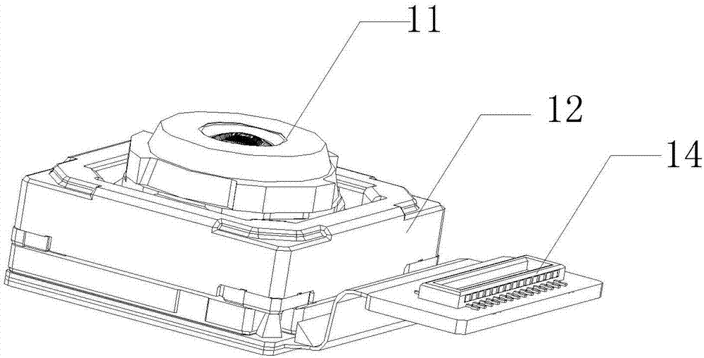
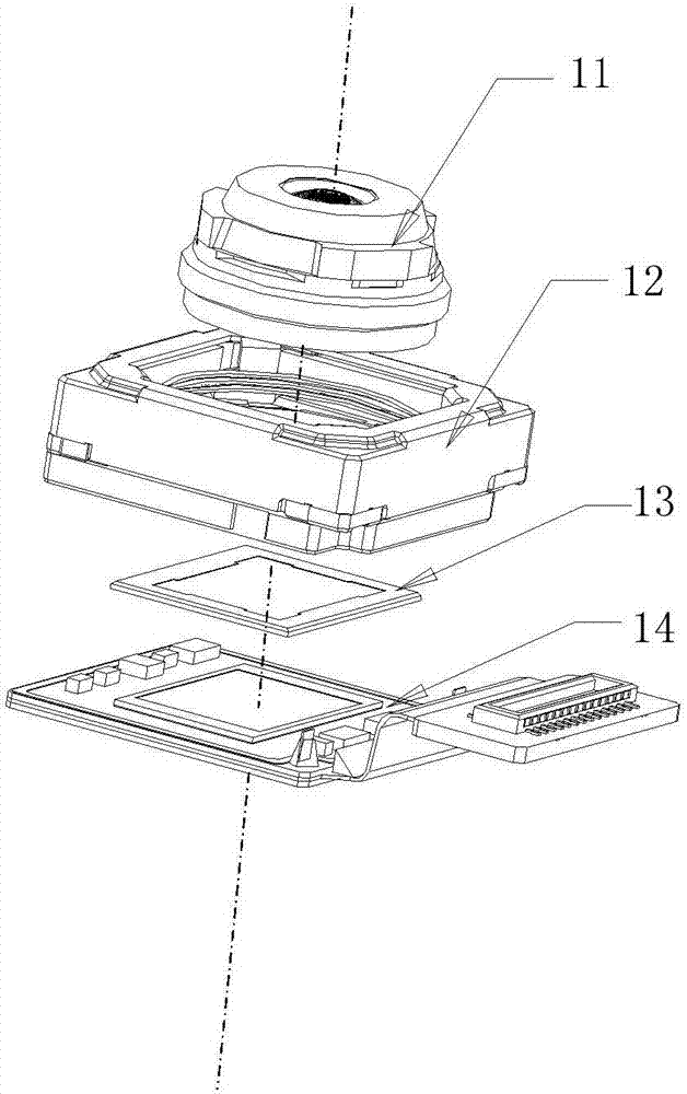
[0085]In this embodiment, the refracting part 400 is fixedly connected with the lighting lens 311 and the first lens 312; the camera body assembly 500 is fixed in the accommodating cavity, and the first assembly passes through the The telescopic mechanism reciprocates in the predetermined direction; wherein, in the first state, the second reflective surface 403 of the refraction part 400 is offset from the second lens 510; in the second state, the lens The assembly 310 protrudes out of the accommodating cavity, and in the second state, the light beam emitted by the second reflective surface 403 of the refraction part 400 faces the camera main assembly 500 .

[0086] Using the above solution, the lens assembly 310 (including the lighting lens 311 and the first lens 312, etc.) 510, focusing motor 523, infrared filter 522, image sensor and line connection substrate 521, etc.) are made as an integral second assembly, and the telescopic mechanism can drive the first assembly indepe...

Embodiment 2

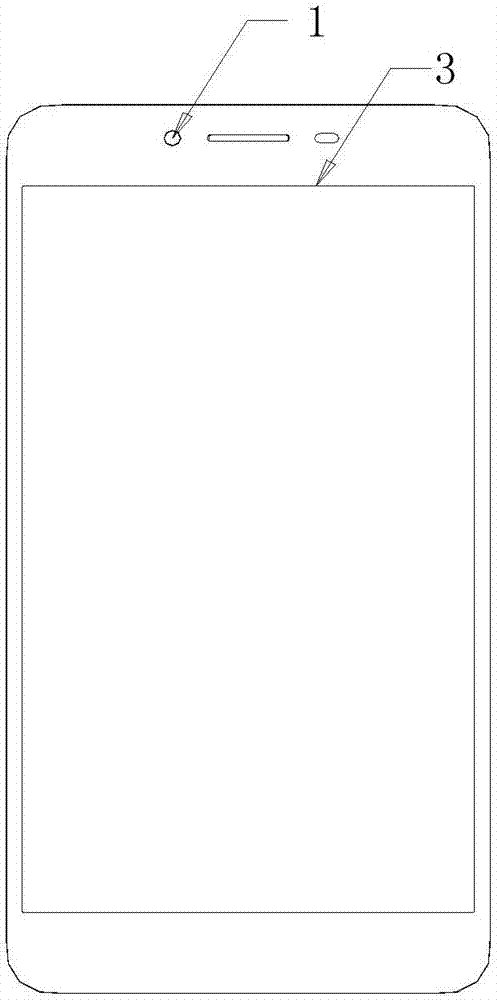
[0090] In this embodiment, the refracting part 400 is fixed relatively to the lens assembly 310 and the camera body assembly 500, wherein, in the first state, the camera module 10 is housed in the In the accommodating cavity; in the second state, the lens assembly 310 of the camera module 10 protrudes out of the accommodating cavity from the opening.

[0091] With the above solution, the telescopic mechanism can drive the entire camera module 10 to translate in the predetermined direction, and the lens assembly 310, the refraction part 400 and the 510 camera main assembly 500 are always kept relatively fixed, in,

[0092] When the camera does not need to be used (that is, in the first state), the telescopic mechanism moves the entire camera module 10 into the accommodating cavity of the device casing 200 along the predetermined direction, so that the entire camera module 10 is retracted to the device casing 200 in the holding chamber;

[0093] When the camera needs to be use...


PUM


Abstract

The invention provides a terminal device, comprising a display screen and a device shell, wherein a containing cavity is formed between the display screen and the device shell, and an opening is arranged on a frame of the device shell; a camera module which comprises a lens assembly for collecting light and a camera body assembly for receiving the light collected by the lens assembly and forming image information; and a flexible mechanism, wherein the flexible mechanism controls the camera module to carry out reciprocating motion in the containing cavity along a preset direction, so the camera module has a first state and a second state, when the camera module is in the first state, the camera module is contained in the containing cavity, and when the camera module is in the second state, the lens assembly in the camera module stretches out of the containing cavity from the opening, so the light is collected and the collected light is projected to the camera body assembly. According to the terminal device provided by the invention, the camera module can be arranged on the terminal device in a flexible mode, and the problem that in the prior art, a size of the display screen of the terminal device is prevented from being increased due to existence of the camera.

Description

technical field [0001] The present invention relates to the technical field of terminal equipment, in particular to a terminal equipment. Background technique [0002] figure 1 with figure 2 Shown is a simple structural diagram of a camera module on a terminal device such as a mobile phone at present. Such as figure 1 with figure 2 As shown, the current camera module on the terminal device mainly includes a lens assembly 11 and a camera main assembly, wherein the lens assembly 11 is mainly used to capture image light, mainly includes a lighting lens and a plurality of lenses, and the camera main assembly mainly It is used to receive the image light captured by the lens assembly 11 and identify the image light. It is mainly composed of a focus motor 12, an infrared filter segment 13, an image sensor, and a circuit connection substrate 14. These devices are integrated together to form a Complete camera module. [0003] Due to the relatively large structure size of the ...

Claims


Application Information

Patent Timeline
IPC IPC(8): H04N5/225G03B17/17G02B13/00G03B13/34
CPCG02B13/001G03B13/34G03B17/17H04N23/57
Inventor 黄志军
Owner VIVO MOBILE COMM CO LTD
Why Eureka
Try Eureka