
Flag flying rotary type hanging device and air-supply flying device

A rotary and national flag technology, which is applied in the direction of display devices, flags/flags, instruments, etc., can solve the problems of flagpole side obstruction, fixation, and aesthetic impact

Inactive Publication Date: 2010-01-13
高旭奕
View PDF0 Cites 3 Cited by
  • Summary
  • Abstract
  • Description
  • Claims
  • Application Information

AI Technical Summary

Problems solved by technology

Since the lifting pulleys on the top of the existing flagpoles hang the national flag in a fixed direction, there are some defects: when the wind direction meets the direction of the lifting pulleys or is sideways, the flagpoles will be sideways and the national flag will be affected. Huazhan is fluttering and does not adapt well to the implementation of wind fluttering
So just produced a kind of artificial setting (blower fan) air supply fluttering device, because the existing air supply fluttering device is that the wind force provided by the air supply fan is passed through the air supply pipeline through the tube type flagpole or the fan supply handle is set in the tube type flagpole. The wind power is sent to the wind opening on the top of the flagpole, and the national flag can only be fluttered when the national flag is raised to the wind opening. Therefore, there are defects: the vast majority of the flag raising ceremony is from the beginning of the flag raising to the wind opening. The national flag cannot fly and the direction of the wind opening is fixed, which is not suitable for outdoor use, and the wind opening is too large to affect the appearance

Method used


Image

  • Flag flying rotary type hanging device and air-supply flying device
  • Flag flying rotary type hanging device and air-supply flying device
  • Flag flying rotary type hanging device and air-supply flying device

Examples


specific Embodiment approach

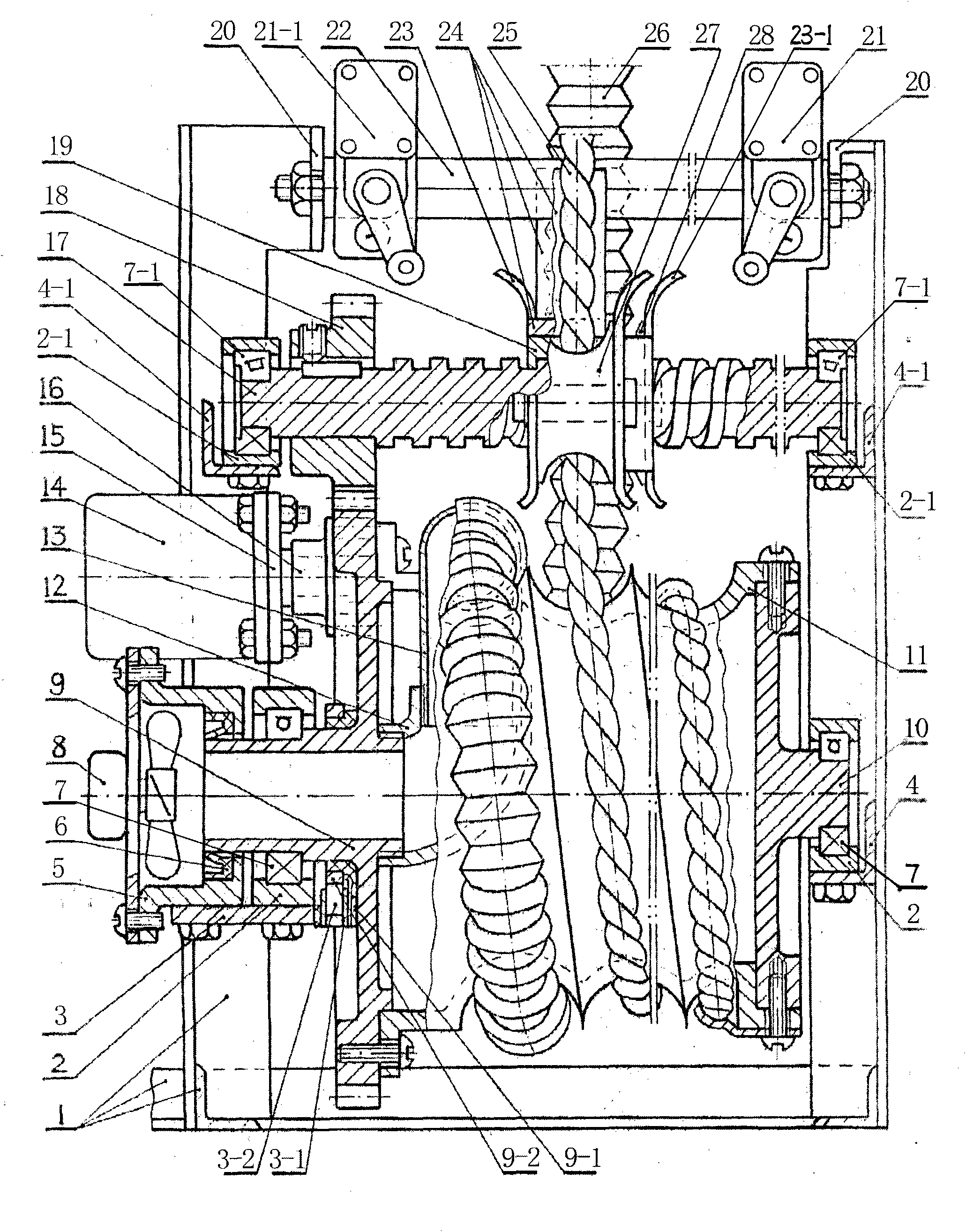
[0088] 2. The air supply pipe (26) wound on the hoist cylinder body (11) in the hoist air supply device of the divided rope pipe is wound during the air supply during the rotation of the hoist cylinder body (11). Two specific implementations are provided: a. The sealing ring is connected to the middle-hole shaft type rotary air supply mode, and a middle-hole gear shaft type cylinder end shaft (9) with a ventilation hole in the center of the rotating shaft is set and the middle hole is used to rotate the shaft. A sealing ring (6) is installed between the ends of the end connected to the fixedly installed fan supply connecting pipe (5), and the center hole gear shaft type cylinder end shaft (9 ) is connected and drives the air supply pipe (26) that is wound up on the hoisting drum cylinder body (11) in rows and can not only rotate but also supply air when stalled. b. Electric slip ring rotating transmission electric combined rotating air supply mode, because the rotation speed o...


PUM


Abstract

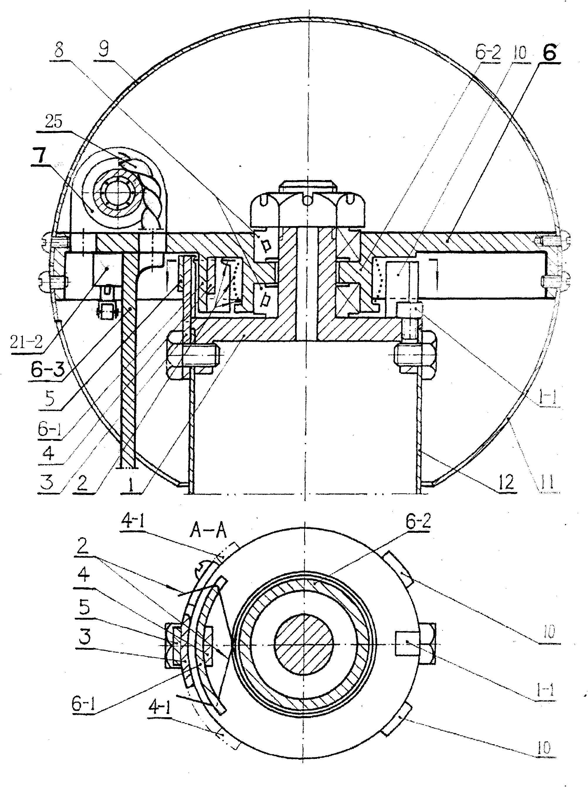
The invention provides a flag flying rotary type hanging device and an air-supply flying device, relating to a flag pole which is used for supply wind to keep a flag flying when wind does not blow; wherein a lifting pulley rotates around the top end of the flag pole. In the flag flying rotary type hanging device, a shaft seat (1) is fixedly arranged on a top end plane of the flag pole (12), and arotating disk (6) is rotatably arranged on the shaft seat (1) by a bearing (8); because the lifting pulley (7) is arranged on the rotating disk (6), a flying flag can pull the rotating disk (6) to deflect correspondingly along with different wind directions; under the effect of torsion force of a torsion spring (2) which is hooked between a torsion spring rotation hanging plate (6-1) and a main-direction hanging plate (3) and is arranged on a bearing torsion spring seat pole (6-2), the deflected rotating disk (6) rotates to a rotating direction selected by the lifting pulley (7) when natural wind is reduced to stop. A flag can fly in different wind directions and supplies a condition for wind supplying and the flying of the flag by.

Description

Technical field: [0001] The utility model relates to the technical field of a flagpole with a lifting pulley rotating around the top of the flagpole and a flagpole for wind-flying flags when there is no wind. Background technique: [0002] The suspension device that the existing national flag flutters and the fluttering device for wind is made up of flagpole, lifting pulley, hoisting rope and supply blower fan, wind exhibition mouth. Since the lifting pulleys on the top of the existing flagpoles hang the national flag in a fixed direction, there are some defects: when the wind direction meets the direction of the lifting pulleys or is sideways, the flagpoles will be sideways and the national flag will be affected. Huazhan is fluttering and does not adapt well to the implementation of wind fluttering. Compared with the modern civilized and harmonious society with high progress in science and technology, economy, material and cultural life, this long-term national flag hangin...

Claims


Application Information

Patent Timeline
IPC IPC(8): G09F17/00E04H12/32
Inventor 高旭奕
Owner 高旭奕
Learn More