Vibrator of beam type linear ultrasonic motor using bending vibration modes

A linear ultrasonic motor, modal technology, applied in the direction of generator/motor, piezoelectric effect/electrostrictive or magnetostrictive motor, electrical components, etc., can solve the problem of low electromechanical coupling efficiency and mechanical output capacity constraints of ultrasonic motor , low tensile strength and other problems, to achieve the effect of improving mechanical output capacity, simple structure, and improved motor performance

Active Publication Date: 2010-01-13
HARBIN INST OF TECH
View PDF0 Cites 40 Cited by
  • Summary
  • Abstract
  • Description
  • Claims
  • Application Information

AI Technical Summary

Problems solved by technology

[0004] The purpose of the present invention is to provide a bending mode beam type linear ultrasonic motor vibrator to solve the problem that the mechanical output capability of the ultrasonic motor is restricted due to the low tensile strength of the ceramic material and the low electromechanical coupling efficiency in the prior art

Method used


Image

  • Vibrator of beam type linear ultrasonic motor using bending vibration modes
  • Vibrator of beam type linear ultrasonic motor using bending vibration modes
  • Vibrator of beam type linear ultrasonic motor using bending vibration modes

Examples


specific Embodiment approach 1

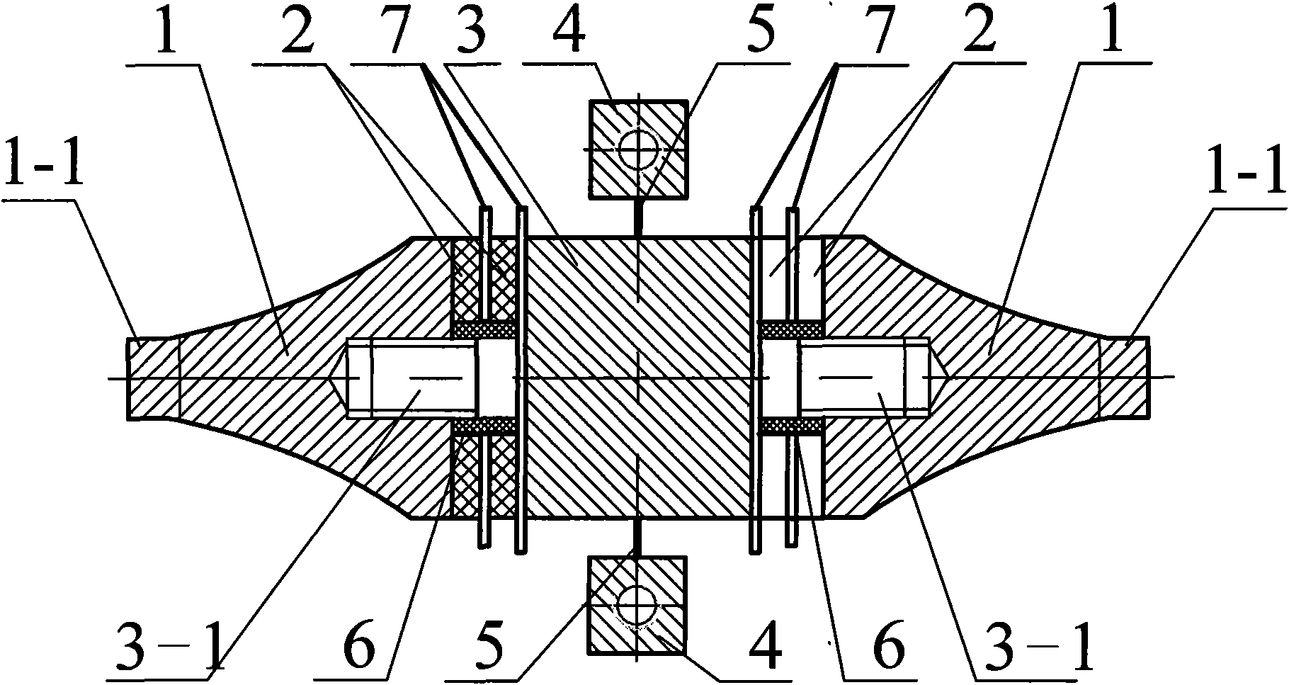
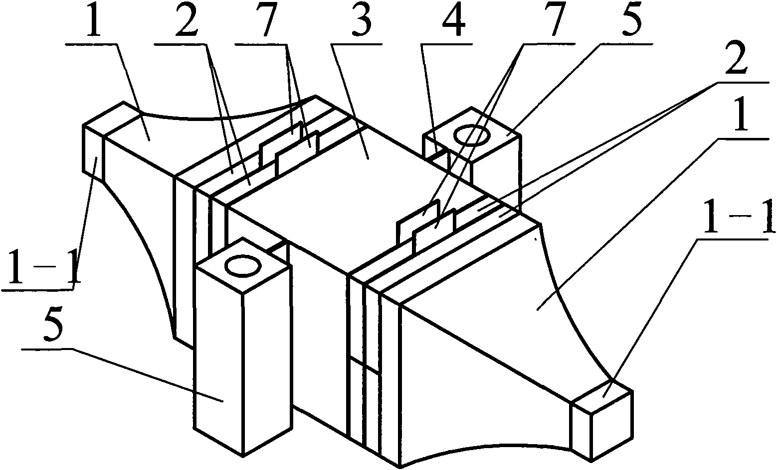
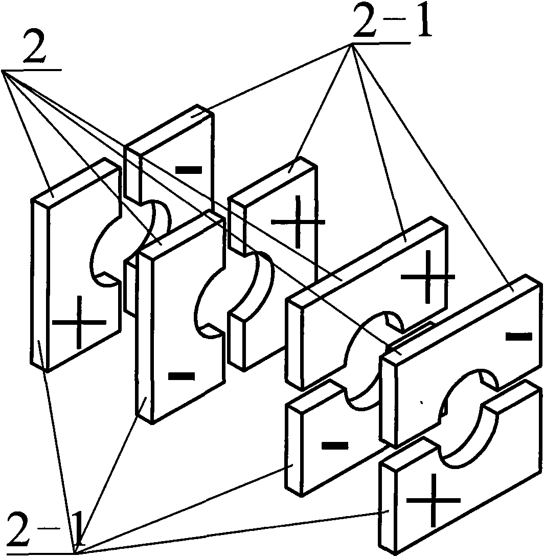
[0008] Specific implementation mode one: the following combination Figure 1 to Figure 3 This embodiment will be specifically described. This embodiment consists of two driving feet 1-1, two end covers 1, two insulating sleeves 6, two pairs of piezoelectric ceramic sheets 2 whose polarization direction is the thickness direction, a flange plate 3, four electrode sheets 7, Composed of two thin-walled beams 5 and two mounting seats 4, a stud 3-1 protrudes from the two end faces of the flange 3 along its axis, and each stud 3-1 is covered with a pair of piezoelectric ceramic sheets 2 and an insulating sleeve 6 is arranged between the stud 3-1 and the piezoelectric ceramic sheet 2, and an end cap 1 is screwed on the overhanging end of each stud 3-1 so that the piezoelectric ceramic sheet 2 is pressed Immediately between the flange 3 and the end cover 1, the end cover 1 is a quadrangular prism with a square cross-section and tapering from its head end to the end, and each end cove...

specific Embodiment approach 2

[0011] Embodiment 2: The difference between this embodiment and the beam-type linear ultrasonic motor vibrator with flexural vibration mode described in Embodiment 1 is that the cross-section of the piezoelectric ceramic sheet 2 is square or circular.


PUM


Abstract

A vibrator of a beam type linear ultrasonic motor using bending vibration modes belongs to the technical field of piezoelectric ultrasonic motors and is used for the piezoelectric ultrasonic motors. The vibrator solves the problem that the mechanical output capabilities of the ultrasonic motors are restricted because of low tensile strength and low electromechanical coupling efficiency of ceramic materials in the prior art. The vibrator comprises two driving pads, two end covers, two insulating sleeves, two pairs of piezoelectric ceramics with polarization directions being thickness directions, a flange, two thin-walled beams and mounting bases; wherein, studs extend out from the end faces of the flange along the axis of the flange; each stud is sleeved with a pair of piezoelectric ceramics; an end cover is screwed at the overhanging end of each stud; the tail end of each end cover is provided with a driving pad; each piezoelectric ceramic is composed of two symmetrical half piezoelectric ceramics which are combined after being split; the polarization directions of the two half piezoelectric ceramics are opposite; the splitting lines of the two pairs of piezoelectric ceramics at both sides of the flange are vertical to each other; the polarization directions of the piezoelectric ceramics in each pair are opposite.

Description

technical field [0001] The invention relates to a bending vibration mode linear ultrasonic motor vibrator, which belongs to the technical field of piezoelectric ultrasonic motors. Background technique [0002] Piezoelectric ultrasonic motor is a kind of piezoelectric ultrasonic motor that uses the inverse piezoelectric effect of piezoelectric ceramics to excite vibration in the ultrasonic frequency range in the elastic body, and forms a particle motion with a specific trajectory at a specific point or area on the surface of the elastic body, and then passes through the stator, The frictional coupling between the rotors converts the microscopic motion of the particle into the macroscopic motion of the rotor. It has the advantages of low speed and high torque, no need for a transmission mechanism, no electromagnetic interference, fast response, and self-locking when power is off. As a piezoelectric driver, it has Very wide range of applications. [0003] Due to the simplicity...

Claims


Application Information

Patent Timeline
Patent Type & Authority Applications(China)
IPC IPC(8): H02N2/04
Inventor 陈维山刘英想石胜君刘军考
Owner HARBIN INST OF TECH
Why Eureka
Try Eureka