
Camera-based lane marker detection

A lane marking and detection system technology, applied in computer components, image analysis, instruments, etc., can solve the problems of indistinguishability, inability to solve the complex environment of slow vehicles, slow operation and processing time, etc., and achieve the effect of low cost

Inactive Publication Date: 2010-01-20
GM GLOBAL TECH OPERATIONS LLC
View PDF0 Cites 14 Cited by
  • Summary
  • Abstract
  • Description
  • Claims
  • Application Information

AI Technical Summary

Problems solved by technology

Most systems work fairly well at high speeds, but can't handle the complex environment of slow traffic
Such camera-based systems are prone to incorrectly distinguishing road objects such as curbs and lane markings from trees, building shadows, and other environmental conditions
Also, camera-based systems are often challenged by situations such as sharp bends in the road or weather / low sun angles
Since turns in the road are more difficult to detect than straight lines, such systems have the disadvantage of running slower processing times for accurate detection of lane markings

Method used


Image

  • Camera-based lane marker detection
  • Camera-based lane marker detection
  • Camera-based lane marker detection

Examples


Embodiment Construction

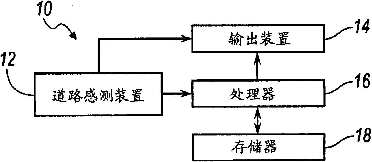
[0021] figure 1 A lane marking detection system 10 for detecting lane markings in a road on which a vehicle is driven is shown in . The lane marking detection system 10 may be used in an autonomous steering system for road detection, or the lane marking detection system 10 may be used as a driver alert for a vehicle driven by a driver during periods of poor road or lane marking visibility during the day or at night or to Increase visibility during other situations while increasing visibility is warranted.

[0022] The lane marking detection system 10 includes an image capture device 12 including, but not limited to, a camera. The image capture device 12 captures an image of the road, typically the area in front of the vehicle. The captured image is processed to identify both sides of the lane marking as well as the line (ie, subject) of the lane marking.

[0023] Lane marking detection system 10 also includes a processor 16 for receiving and processing image data captured b...


PUM


Abstract

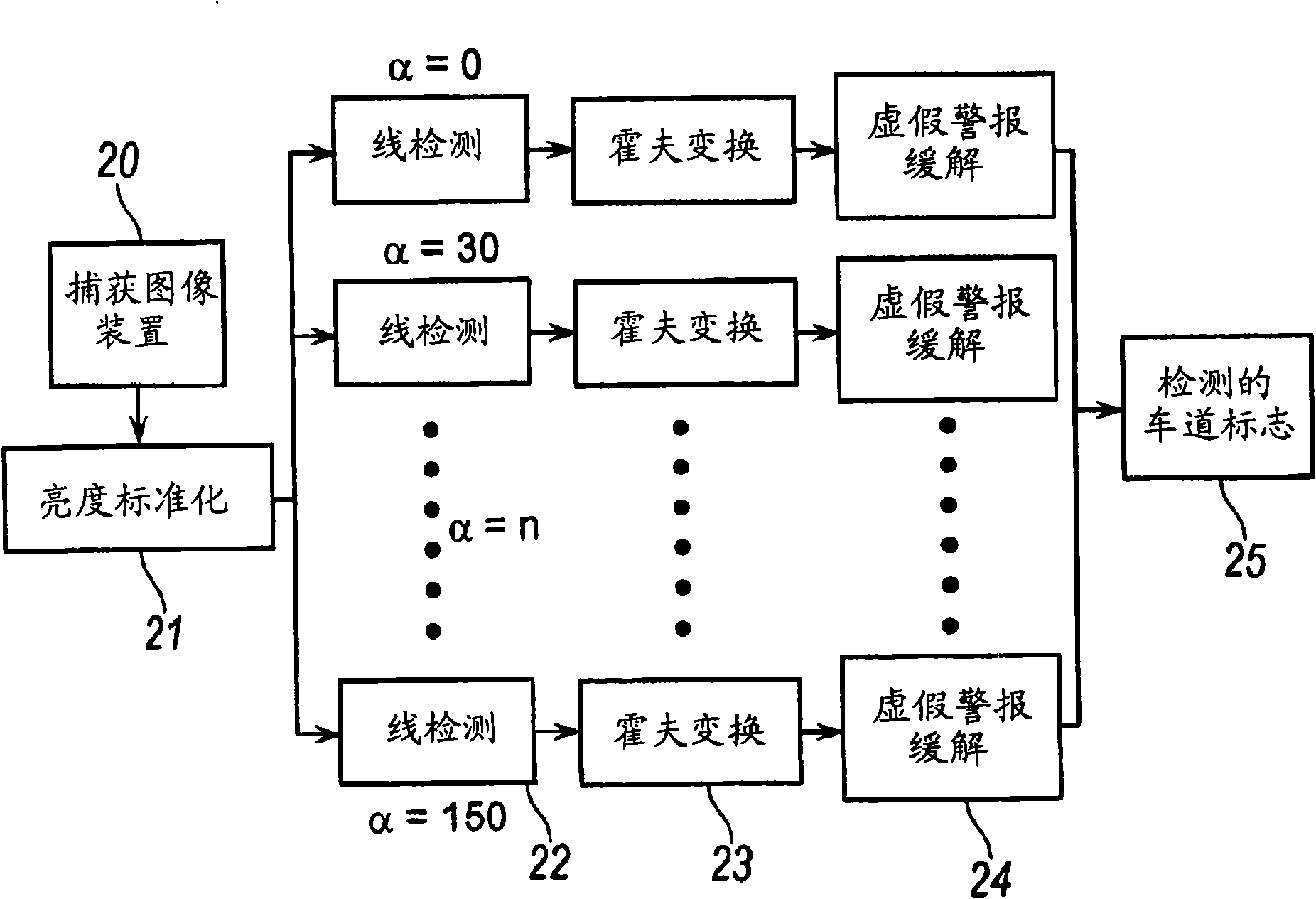
The invention relates to a camera-based lane marker detection. A method is provided for detecting road lane markers in a vehicle road using an imaging device. Road input data is captured using the imaging device. Lighting normalization is applied to the road input data. The method detects the road lane markers in a few main orientations in the normalized input data. In each main orientation, the normalized input data is convolved with an oriented edge detection filter for generating an oriented edge-based filter response. The normalized input data is convolved with an oriented line detection filter for generating an oriented line-based filter response. Candidate lane markers are selected in response to the edge-based filter response and line-based filter response in each main orientation. A transformation technique is applied to the candidate lane markers for identifying the lane markings in each main orientation.

Description

technical field [0001] The present invention generally relates to lane marking detection of roads using image capture devices. Background technique [0002] Camera-based lane marking detection systems are used to detect road segments of roads or lanes. Most systems work fairly well at high speeds, but cannot handle the complex environment of slow traffic. Such camera-based systems are prone to failing to correctly distinguish road objects such as curbs and lane markings from trees, building shadows, and other environmental conditions. Additionally, camera-based systems are often challenged by certain situations, such as sharp bends in the road or weather / low sun angles. Since turns in the road are more difficult to detect than straight lines, such systems have the disadvantage of running slower processing times for accurate detection of lane markings. Contents of the invention [0003] Advantages of the present invention provide a low cost and reliable detection of lane...

Claims


Application Information

Patent Timeline
Patent Type & Authority Applications(China)
IPC IPC(8): G06T7/00
CPCG06K9/00798G06V20/588
Inventor W·张V·萨德卡
Owner GM GLOBAL TECH OPERATIONS LLC
Learn More