Grating

A grid and longitudinal rib technology, applied in the field of manufacturing the above-mentioned types of covered grids, can solve the problems of inability to further reduce the thickness of the plate, insufficient load transfer, and low connection strength.

Active Publication Date: 2010-01-20
ACO SEVERIN AHLMANN GMBH & CO KG
View PDF1 Cites 8 Cited by
  • Summary
  • Abstract
  • Description
  • Claims
  • Application Information

AI Technical Summary

Problems solved by technology

[0007] However, the aforementioned covering grids made of sheet metal have the disadvantage that, despite the use of longitudinal ribs, the load transmission, especially in the transverse direction, is not sufficient and therefore the

Method used


Image

  • Grating
  • Grating
  • Grating

Examples


Embodiment Construction

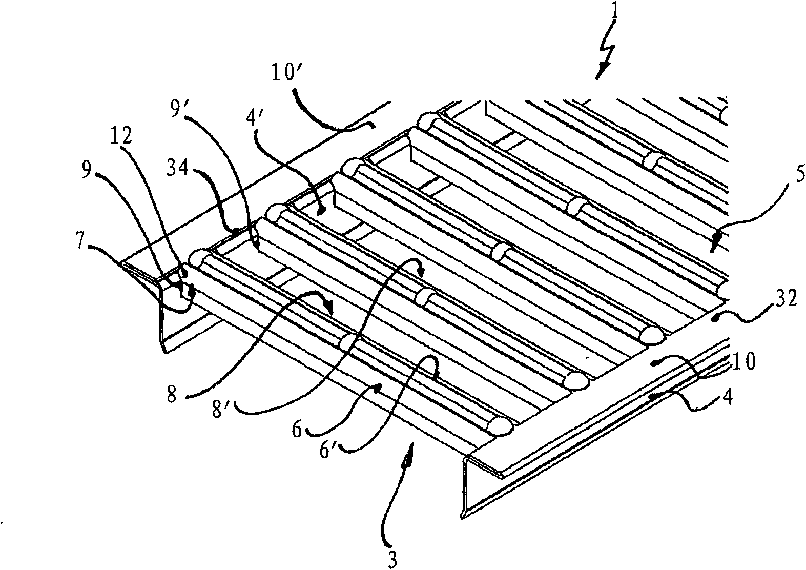
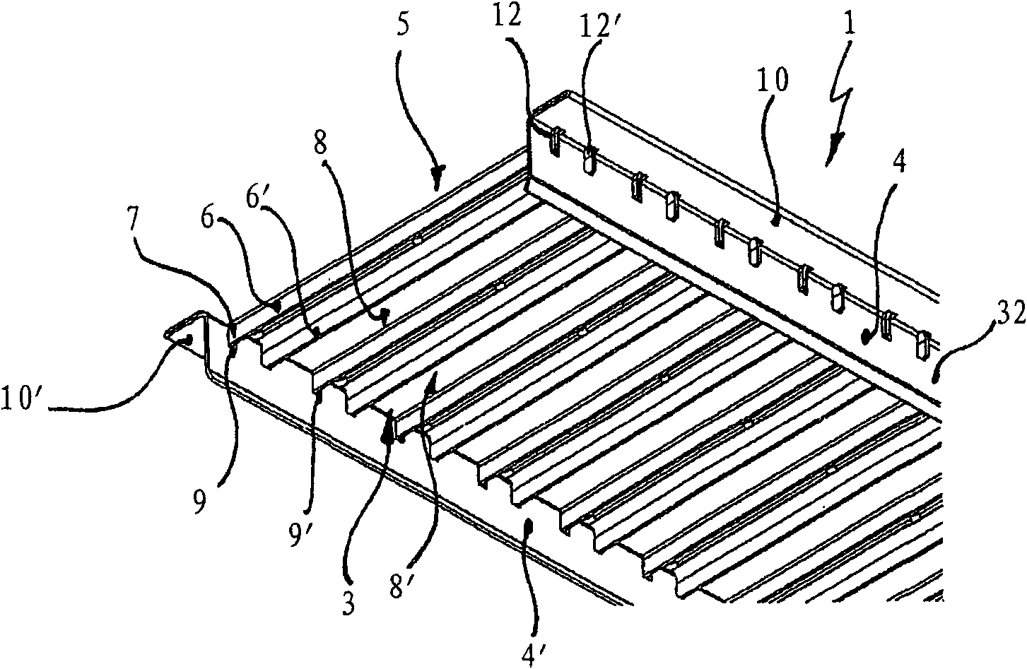
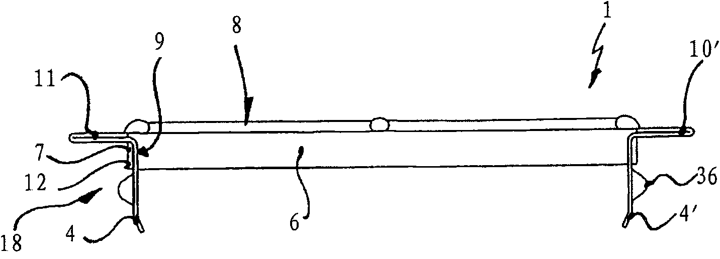
[0031] figure 1 with figure 2 Each shows an isometric view of a first embodiment of a covering grid 1 according to the invention. The cover grid shown here is formed by flanging a sheet metal 32 and has longitudinal ribs 4 formed in one piece with the cover grid 1 . The longitudinal ribs 4 are formed from a sheet metal that has been folded several times, thereby additionally forming a support area 10 for laying the covering grate 1 on a drainage pipe (not shown).

[0032] Furthermore, the cover grid 1 has a plurality of inflow channels 8 which can be used in particular for conducting surface water or the like. Basically, the term inflow slot is intended to be understood as meaning almost any inflow opening extending essentially between two longitudinal ribs 4 of the cover grid 1 .

[0033] In this case, the inflow channels 8 are stamped and formed from sheet metal 32 and each have two transverse ribs 6 which each extend parallel to the inflow channels 8 on the underside 3 ...


PUM


Abstract

A cover grating for a drainage channel (20) or a similar hollow body which can be installed in the ground is presented, comprising at least two longitudinal webs (4) extending on a lower side (3) of the cover grating (1) and inlet slots (8) formed in the cover grating (1) between these longitudinal webs (4), and comprising transverse webs (6) resulting from the slot-forming operation and extending on the lower side (3) of the cover grating (1), wherein the transverse webs (6) are provided at each of their end regions (7) with at least one receiving projection (12) which at least partially engages into a respective complementarily formed receiving slot (9) in the longitudinal web (4).

Description

technical field [0001] The invention relates to a covering grating for drainage pipes or similar hollow bodies which can be installed into the ground, the covering grating having at least two longitudinal ribs extending on the underside of the covering grating and between these The inflow channels formed in the cover grid between the longitudinal ribs have transverse ribs extending on the underside of the cover grid as a result of said forming. [0002] Furthermore, the invention relates to a method for producing a cover grid of the above-mentioned type. Background technique [0003] Such covering gratings are known from the prior art and are mainly used for covering rain gutters, floor drains, manholes or similar hollow bodies which can be installed in the ground. The cover grid is preferably placed on the upper edge of the hollow body or on a frame formed on the upper edge of the hollow body. Depending on the type of installation site, this covering grille is subjected t...

Claims


Application Information

Patent Timeline
IPC IPC(8): E03F5/06
CPCE03F2005/063E03F2005/065E03F5/06
Inventor 阿克塞尔·拉思曼汉斯-朱利叶斯·阿尔曼
Owner ACO SEVERIN AHLMANN GMBH & CO KG
Why Eureka
Try Eureka