Buckling structure

A buckle structure and buckle parts technology, which is applied in the direction of cabinet/cabinet/drawer components, mechanical equipment, fixing devices, etc., can solve problems such as inconvenient operation, easy falling of screws, and broken hooks, etc., to achieve Improve convenience and solve the effect of difficult disassembly

Inactive Publication Date: 2010-01-27
INVENTEC CORP
View PDF0 Cites 53 Cited by
  • Summary
  • Abstract
  • Description
  • Claims
  • Application Information

AI Technical Summary

Problems solved by technology

[0004] In the design of the assembly structure of the casing, screws are often used as fixing parts to lock the casing; however, in the fixing technology using screws, a tool of corresponding size, such as a screwdriver (screwdriver), must be selected according to the size of the screw for screwing. Therefore, when repairing electronic products with parts of many sizes, tools must be replaced frequently, which causes a lot of inconvenience, especially for places where parts are densely packed, it is difficult to operate tools such as screwdrivers to make the screw lock or Unscrewing, even special tools must be specially designed to provide assembly and disassembly; therefore, the fixing technology using screws has the disadvantages of inconvenient operation and time-consuming
[0005] In addition, if the screw is not fixed firmly and automatically loosens, the loose screw will easily fall to the circuit board inside the casing, which will affect the normal operation of the circuit board. What's more, the screw will touch the circuit board The circuit caused by the circuit short circuit, and then the circuit board burned
[0006] Furthermore, there are also snap-fit ​​structures for assembling the case, for example, hooks and slots are interlocked to achieve the purpose of assembling the case; Therefore, when vibration or temperature change occurs, for example, the hook is likely to be deformed and over-clamped with the slot, which makes it difficult for the user to separate the hook and slot during the process of disassembling the case. It will cause the hook to break and damage the buckle structure, so that the casing can no longer be assembled

Method used


Image

  • Buckling structure
  • Buckling structure
  • Buckling structure

Examples


Embodiment Construction

[0030] Embodiments of the present invention are described below through specific examples, and those skilled in the art can easily understand other advantages and effects of the present invention from the content disclosed in this specification.

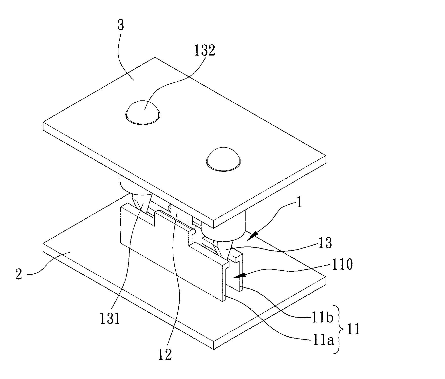
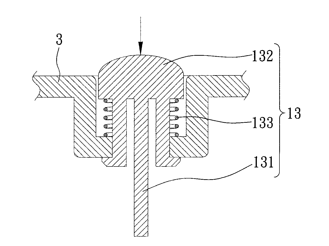
[0031] see figure 1 , is a three-dimensional combined schematic view of the buckle structure 1 and the first and second shells 2 and 3 applied to the buckle structure 1 of the present invention; as shown in the figure, the present invention provides a method for fixing the first shell 2 and the buckle structure 1 of the second housing 3 , the buckle structure 1 includes a first buckle 11 , a second buckle 12 and an unlocking piece 13 .

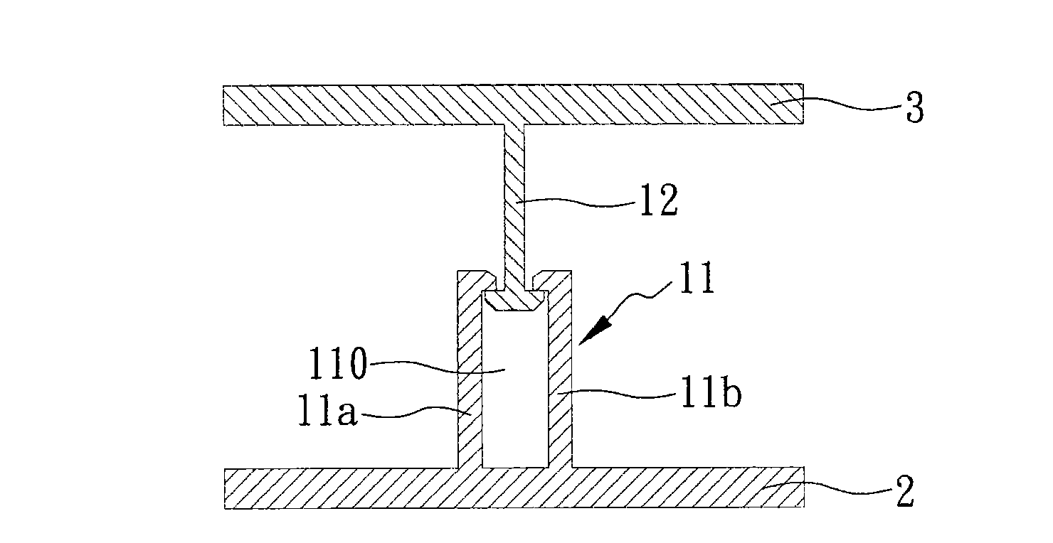
[0032] The first buckle 11 is disposed on the first housing 2. In this embodiment, the first buckle 11 is two first hooks arranged on the first housing 2 at intervals corresponding to each other. 11a and 11b, the first hooks 11a and 11b are L-shaped and arranged in opposite directions (ie hook to ho...


PUM


Abstract

The invention relates to a buckling structure which is used for fixing a first shell and a second shell. The buckling structure comprises a first buckling part, a second buckling part and a debuckling part, wherein the first buckling part is arranged on the first shell; the second buckling part is arranged on the second shell, corresponds to the first buckling part and is in fit with the first buckling part; and the debuckling part is arranged on the second shell and corresponds to the first buckling part. The second buckling part is pressed to be mutually buckled with the first buckling part so as to make the first shell and the second shell to be mutually buckled, and the debuckling part is used for pressing to separate the first buckling part and the second buckling part on respective buckled parts when the first buckling part and the second buckling part are mutually buckled, so the aim of detaching the first shell and the second shell without a tool is achieved.

Description

technical field [0001] The invention relates to a buckle structure, in particular to a buckle structure that is easy to disassemble. Background technique [0002] With the improvement of industrial technology and the division of labor, the manufacture of a single product usually goes through many different production processes, such as component manufacturing, assembly, testing, packaging, etc., especially for electronic products. [0003] Due to the miniaturization and multi-functionalization of electronic products, powerful electronic products often integrate a variety of components, and various components belong to different technical fields. It is manufactured by different manufacturers, and finally integrated and assembled through, for example, the casing. Therefore, the assembly structure and electrical connection between different parts are the most critical to the overall effectiveness of electronic products, especially the assembly structure design of the casing is...

Claims


Application Information

Patent Timeline
Patent Type & Authority Applications(China)
IPC IPC(8): F16B1/04H05K5/03
Inventor 王士强黄瑞贤
Owner INVENTEC CORP
Why Eureka
Try Eureka