Engine rear end power takeoff

A technology for power take-off and engine, applied in the direction of engine components, machines/engines, mechanical equipment, etc., can solve the problems of crowded internal space of the engine, increased manufacturing costs, high noise, etc., to save installation space, reduce production costs, and solve Difficulty in disassembly

Inactive Publication Date: 2018-02-23
HUBEI SENYU GEAR DRIVE CO LTD
View PDF0 Cites 3 Cited by
  • Summary
  • Abstract
  • Description
  • Claims
  • Application Information

AI Technical Summary

Problems solved by technology

[0004] Although the current rear-end power take-off overcomes the shortcomings of small output torque and high noise of the front-end power take-off, the casing of the current power take-off and the casing of the engine flywheel are cast into an integral structure, resulting in disassembly and assembly of the power take-off. It is very inconvenient, and the lubrication of the bearings in the power take-off needs to be realized through the external oil passage, which not only causes the inner space of the engine to be crowded, but also increases the manufacturing cost

Method used


Image

  • Engine rear end power takeoff
  • Engine rear end power takeoff

Examples


Embodiment Construction

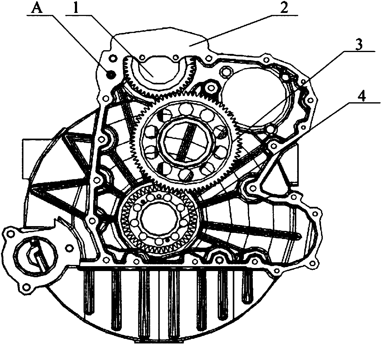
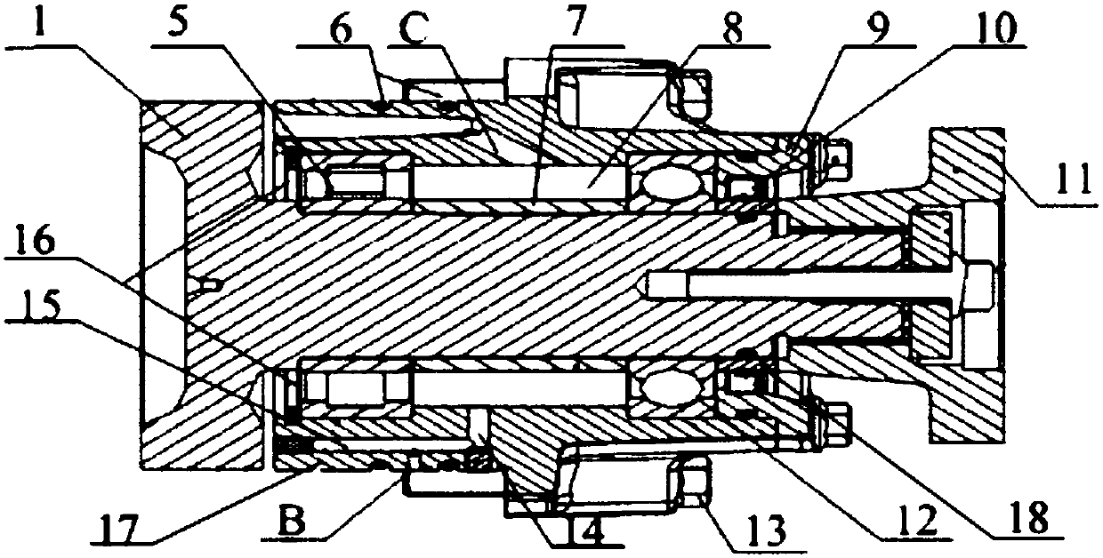
[0025] The core of the present invention is to provide a power take-off at the rear end of the engine. The power take-off at the rear end of the engine is embedded in the flywheel shell by adopting a detachable power take-off shell, which effectively solves the difficult problem of disassembly and assembly of the power take-off At the same time, the part of the power take-off at the rear end of the engine provided by the present invention is embedded in the flywheel housing is also provided with a lubricating oil channel communicating with the bearing cavity in the casing of the power take-off, thereby realizing the internal direct lubrication of the power take-off, The internal installation space of the engine is effectively saved, and the production cost is reduced at the same time.

[0026] In order to enable those skilled in the art to better understand the solutions of the present invention, the present invention will be further described in detail below in conjunction wit...


PUM


Abstract

The invention discloses a power take-off at the rear end of an engine, which includes a power take-off input end, a power take-off output end and a power take-off housing. A bearing cavity for installing a bearing is arranged inside the power take-off housing. The power take-off housing can be embedded in the flywheel housing and can be detachably connected with the flywheel housing, and the part of the power take-off housing embedded in the flywheel housing is provided with the bearing cavity Connected lubricating oil passage. Since its housing can be embedded in the flywheel housing and is detachably connected with the flywheel housing, it effectively solves the problem of difficult disassembly and assembly of the power take-off at the rear end of the engine at present. The part of the flywheel housing is also provided with a lubricating oil channel that communicates with the bearing cavity in the PTO housing, so as to realize direct lubrication inside the PTO. Compared with the current way of using external oil channels to lubricate the internal bearings of the PTO, Not only the installation space inside the engine is saved, but also the production cost is reduced.

Description

technical field [0001] The invention relates to the technical field of engine power take-offs, in particular to an engine rear end power take-off. Background technique [0002] With the continuous development of society, the demand for heavy-duty cement mixer trucks and large-tonnage special vehicles in the market has increased greatly, and there has been a lack of matching between the power take-off device of the engine and the power system of the vehicle, which seriously affects the power system at the upper end of the engine. The main reason is that the power take-off is mainly directly driven by the belt through the crankshaft pulley at the front end, which not only has the disadvantages of small output torque and high noise, but also easily causes damage to the power take-off device and even the engine itself. shortened lifespan. [0003] Therefore, a rear-end power take-off driven by the crankshaft gear at the rear end of the engine is produced. The main working princ...

Claims


Application Information

Patent Timeline
Patent Type & Authority Applications(China)
IPC IPC(8): F02B61/06F02B67/06F02B77/00
CPCF02B61/06F02B67/06F02B77/00
Inventor 杨斌
Owner HUBEI SENYU GEAR DRIVE CO LTD
Why Eureka
Try Eureka