
Sunlight collecting device

A technology for collecting devices and sunlight, applied in solar thermal devices, heating devices, optics, etc., can solve problems such as being easily affected by ambient temperature, additional space required for rotation, and water leakage

Inactive Publication Date: 2010-01-27
TSMTECH
View PDF0 Cites 9 Cited by
  • Summary
  • Abstract
  • Description
  • Claims
  • Application Information

AI Technical Summary

Problems solved by technology

[0002] In the past, the traditional light collecting device formed an opening on the top floor of the building and installed a glass cover to allow light to enter the room. In addition to damaging the structure of the building, it is also prone to water leakage and it is not easy to improve the light collection. Efficient and difficult to redistribute sunlight to other floors or rooms in the building
In the traditional technology, it is also mentioned that a sensor can be installed to detect the operating position of the sunlight, and at the same time, the electromechanical system is used to rotate the light collecting device to align it with the sunlight. However, the sensor is expensive and is easily affected by the ambient temperature. This necessitates a complex thermal design and additional space for rotation, while the electromechanical system is prone to failure and consumes power that negates the benefits of energy savings

Method used


Image

  • Sunlight collecting device
  • Sunlight collecting device

Examples


Embodiment Construction

[0019] In order to make the above-mentioned and other objects, features and advantages of the present invention more comprehensible, the preferred embodiments are listed below, together with the accompanying drawings, and are described in detail as follows:

[0020] In the following embodiments of the present invention, the structure and operating principle of the solar light collection device are mainly described respectively, but these embodiments are only used to illustrate the present invention rather than limit the scope of the present invention.

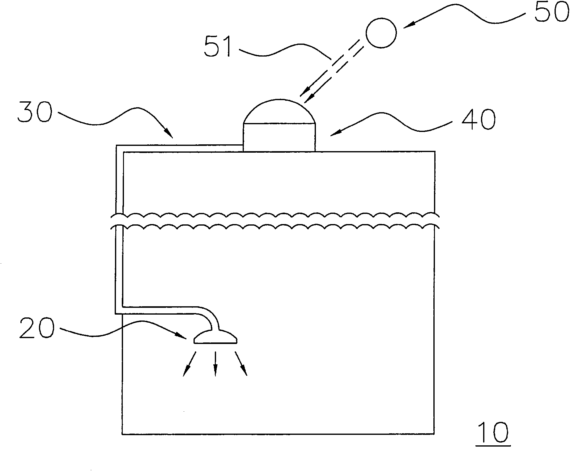
[0021] see figure 1 , the main body 40 of the solar light collecting device is disposed on a building 10, such as a space on the top floor. Meanwhile, a light guiding device 30 is coupled to the main body 40 of the light collecting device, and can enter the room along the side wall of the building. In this way, the light 51 emitted by the sun 50 can be received by the main body 40 of the solar light collecting device, and at t...


PUM


Abstract

The invention discloses a sunlight collecting device, which comprises a light collecting unit and a light guide device, wherein the light collecting unit comprises a light emitting surface and a light receiving surface which has a cambered convex outline; the light collecting unit consists of a plurality of convex lenses; each convex lens is provided with a first end face with a larger area and a second end face with a smaller area; the first end faces are distributed on the cambered convex outline of the light receiving surface to collect sunlight; the second end faces are respectively coupled with an optical fiber; the optical fibers are parallel mutually adjacent to the light emitting surface; and the light guide device is coupled with the light emitting surface of the light collecting unit so as to introduce the collected sunlight. Electromechanical equipment is not required to be arranged in the sunlight collecting device, so the cost is lowered and the fault rate is reduced. Besides, the sunlight collecting device does not absorb the sunlight in a rotating mode, so the additional rotating space occupied by the sunlight collecting device is not required to be considered, and the sunlight can be effectively introduced into a building.

Description

technical field [0001] The present invention relates to a light collection device, and in particular to a sunlight collection device. Background technique [0002] In the past, the traditional light collecting device formed an opening on the top floor of the building and installed a glass cover to allow light to enter the room. In addition to damaging the structure of the building, it is also prone to water leakage and it is not easy to improve the light collection. Efficient and difficult to redistribute sunlight to other floors or rooms in the building. In the traditional technology, it is also mentioned that a sensor can be installed to detect the operating position of the sunlight, and at the same time, the electromechanical system is used to rotate the light collecting device to align it with the sunlight. However, the sensor is expensive and is easily affected by the ambient temperature. This necessitates a complex cooling design and additional space for rotation, whi...

Claims


Application Information

Patent Timeline
IPC IPC(8): G02B19/00G02B6/00G02B6/32F24J2/08
CPCY02B10/20
Inventor 游朱义
Owner TSMTECH
Learn More